Switching voltage stabilizing circuit and control circuit and method thereof

A switching voltage stabilization and control circuit technology, applied in high-efficiency power electronic conversion, electrical components, output power conversion devices, etc., can solve problems such as heat generation and power loss increase, so as to avoid power loss and reduce heat problems , to avoid the effect of continuous increase

Active Publication Date: 2012-08-22
CHENGDU MONOLITHIC POWER SYST
View PDF5 Cites 13 Cited by
  • Summary
  • Abstract
  • Description
  • Claims
  • Application Information

AI Technical Summary

Problems solved by technology

However, in this control mode, when the output power of the switching regulator circuit reaches the maximum power (that is,

Method used


Image

  • Switching voltage stabilizing circuit and control circuit and method thereof
  • Switching voltage stabilizing circuit and control circuit and method thereof
  • Switching voltage stabilizing circuit and control circuit and method thereof

Examples


Embodiment Construction

[0019] Specific embodiments of the present invention will be described in detail below, and it should be noted that the embodiments described here are only for illustration, not for limiting the present invention. In the following description, numerous specific details are set forth in order to provide a thorough understanding of the present invention. It will be apparent, however, to one of ordinary skill in the art that these specific details need not be employed to practice the present invention. In other instances, well-known circuits, materials or methods have not been described in detail in order to avoid obscuring the present invention.

[0020] Throughout this specification, reference to "one embodiment," "an embodiment," "an example," or "example" means that a particular feature, structure, or characteristic described in connection with the embodiment or example is included in the present invention. In at least one embodiment. Thus, appearances of the phrases "in on...


PUM


Abstract

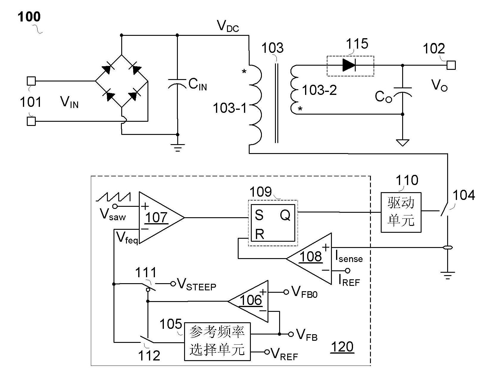
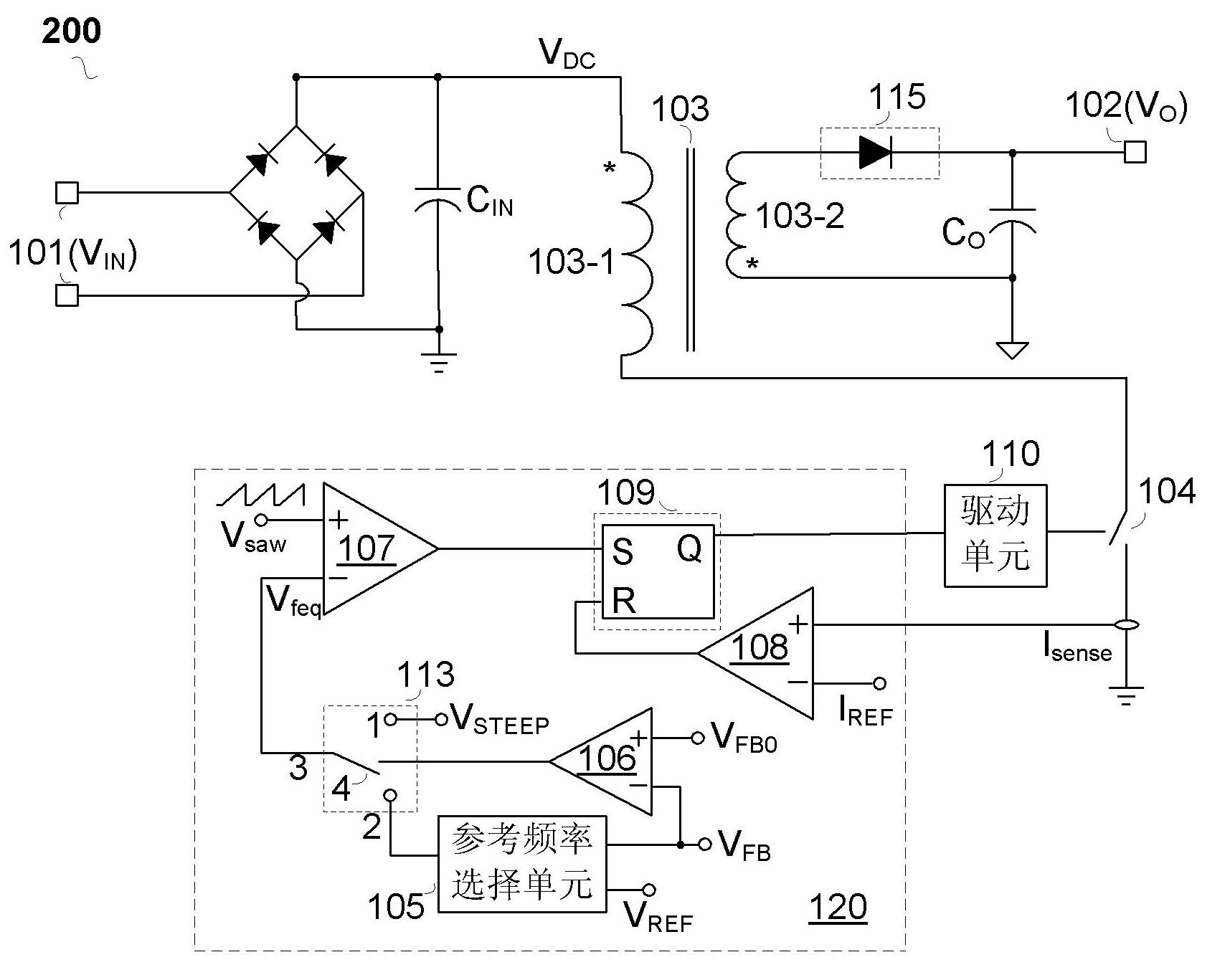
The invention discloses a switching voltage stabilizing circuit and a control circuit and method thereof. The switching voltage stabilizing circuit comprises an input port, an output port, an energy storage element, a main switch, a reference frequency selection unit, a load state detection unit, a first comparator, a current comparator and a logic unit. The switching frequency of the switching voltage stabilizing circuit is quickly improved to be the maximum when the load is the maximum, the continuous improvement of the switching frequency at this time is prevented, so that the continuous improvement of power loss is prevented, and the heat problem is relieved. According to the embodiment of the invention, when the switching voltage stabilizing circuit works under the maximum load, the heat problem is further solved through a continuous time setting unit, so that the performance of a system is better.

Description

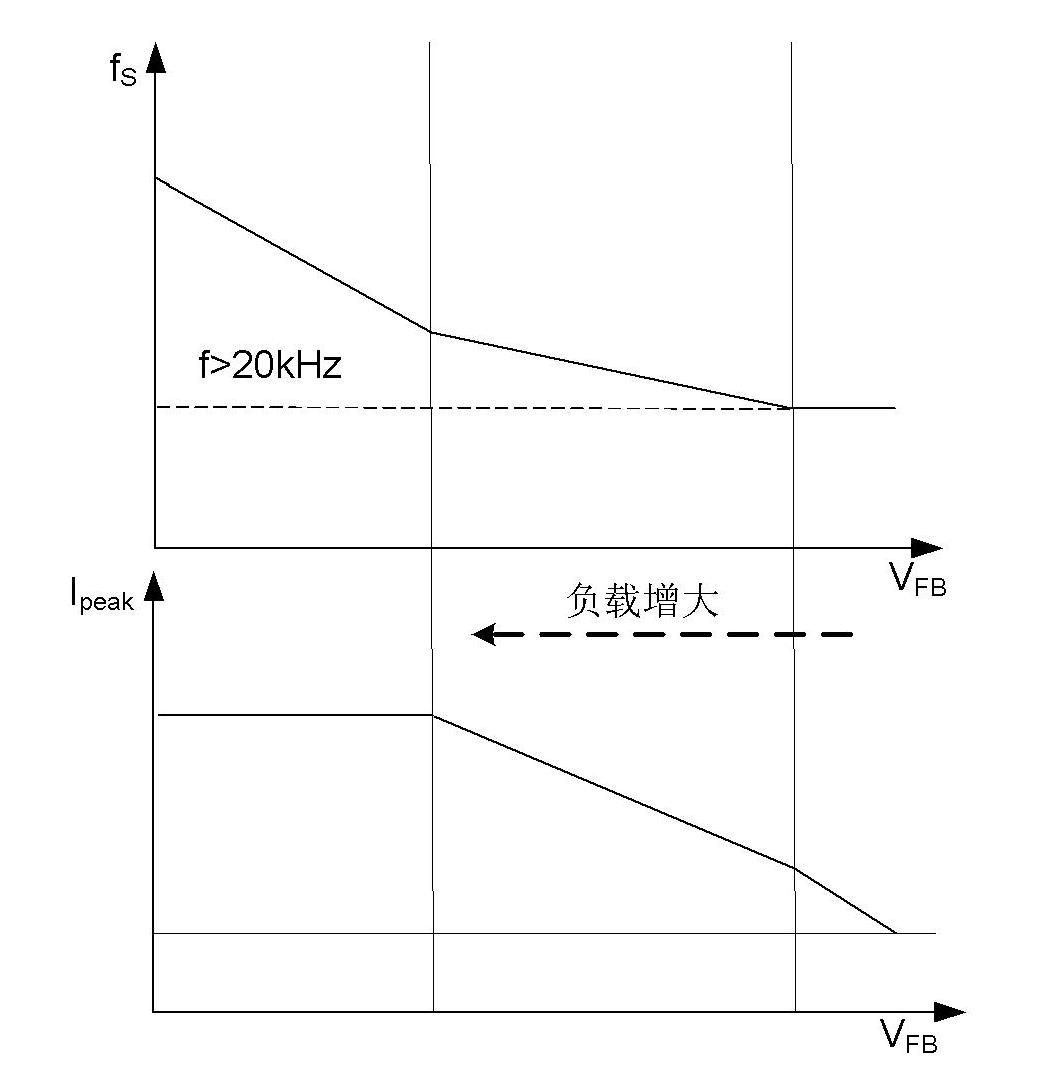
technical field [0001] The present invention relates to an electronic circuit, more specifically, the present invention relates to a switching voltage stabilizing circuit and its control circuit and method. Background technique [0002] Switching regulator circuits are widely used in various occasions. However, the existing switching regulator circuit usually adopts the method of constant peak current or constant switching frequency, so that when the load of the circuit becomes lower, the efficiency decreases. [0003] A prior art uses a multi-mode control method to reduce the switching frequency and peak current when the load of the switching regulator circuit becomes low, thereby improving the working efficiency in the entire load range, such as figure 1 The switching frequency f of the switching regulator circuit shown S and peak current I peak With the feedback signal V reflecting the load status FB The waveform diagram that changes with the change. Among them, the ...

Claims


Application Information

Patent Timeline
IPC IPC(8): H02M1/08H02M1/06
CPCH02M3/33507Y02B70/10H02M1/0032H02M3/33515
Inventor 俞杨威任远程张军明林思聪赵剑
Owner CHENGDU MONOLITHIC POWER SYST
Why Eureka
Try Eureka