
Switching mechanism of magnetic storage cell and logic unit using current induced domain wall motions

a technology of logic units and magnetic storage cells, applied in the field of magnetic storage cells, can solve problems such as degradation of many memory devices, repeated large current flow,

Inactive Publication Date: 2014-03-06
MASSACHUSETTS INST OF TECH
View PDF4 Cites 13 Cited by
  • Summary
  • Abstract
  • Description
  • Claims
  • Application Information

AI Technical Summary

Benefits of technology

The invention provides a magnetic memory cell with a free layer that can be pinned on both sides to form domain wall structures. These structures define logic states by controlling the motion of the domain walls. The invention also includes a method for making the memory cell by providing a free layer and forming domain wall structures that define logic states. The technical effect of this invention is to provide a reliable and efficient way to create a magnetic memory cell with enhanced data retention and stability.

Problems solved by technology

However, in the spin transfer torque based switching mechanism in which current flows perpendicularly to the film surface, large current must flow repeatedly.
Accordingly, dielectric breakdown and pin holes are often generated in the barrier layer, and the interconnections are often broken by the electromigration.
This causes degradation in many memory devices.

Method used


Image

  • Switching mechanism of magnetic storage cell and logic unit using current induced domain wall motions
  • Switching mechanism of magnetic storage cell and logic unit using current induced domain wall motions
  • Switching mechanism of magnetic storage cell and logic unit using current induced domain wall motions

Examples


Embodiment Construction

[0011]The invention involves a switching mechanism for magnetic memory and logic devices. Instead of using the conventional magnetic field switching or spin transfer torque (STT) switching, the inventive device can be toggled between the “0” and “1” states by controlled motion of domain walls.

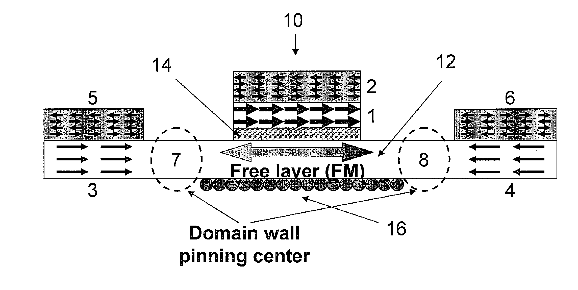
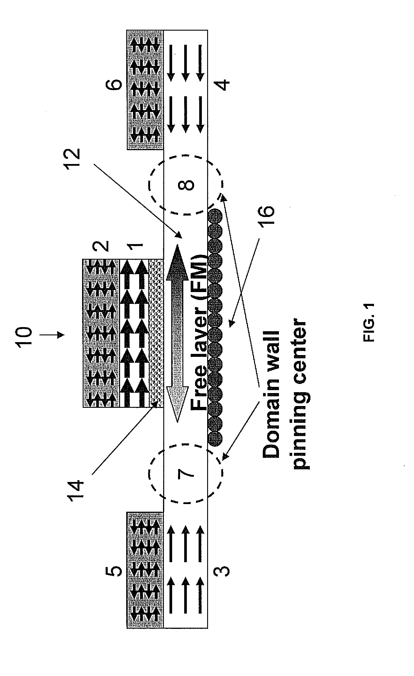
[0012]FIG. 1 illustrates how such a writing process works. In a GMR or TMR based memory / logic unit 10, a ferromagnetic (FM) layer 1 is pinned by current exchange biasing from an anti-ferromagnetic (AFM) layer 2. Another FM or free layer 12 is also provided. The free layer 12 includes regions 7, 8 defining domain wall pinning centers, and pinned regions 3, 4. The free layer 12 is pinned on both of its sides as shown by regions 7, 8, which define the position of a domain wall. An AFM layer 5 pins region 3 of the free layer 12, and an AFM layer 6 pins region 4 of the free layer 12.

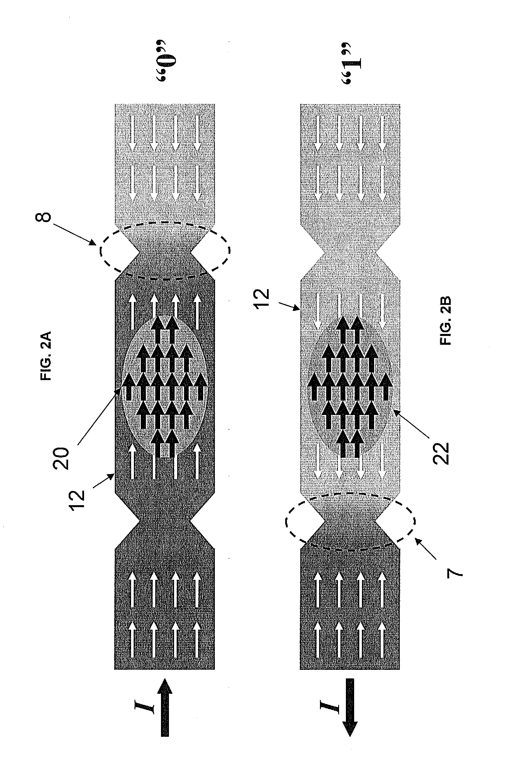
[0013]The memory / logic unit 10 can either be at its “0” or “1” state depending on the position of the domain wall pinn...


PUM


Abstract

A magnetic memory cell is provided that includes a free layer that is pinned on both of its sides to form one or more domain wall structures. The one or more domain wall structures define one or more logic states by controlling the motion of the one or more domain wall structures.

Description

PRIORITY INFORMATION[0001]The present invention claims priority to U.S. Provisional application No. 61 / 314,256, filed on Mar. 16, 2010. The contents of which are incorporated herein by reference in its entirety.SPONSORSHIP INFORMATION[0002]This invention was made with government funding under Grant No. N00014-06-1-0235, awarded by the Office of Naval Research and under Grant No. W911NF-08-1-0087, awarded by the Army Research Office. The government has certain rights in this invention.BACKGROUND OF THE INVENTION[0003]The invention is related to the field of magnetic storage cells, and in particular to a switching mechanism for magnetic storage cells and logic units using current induced domain wall motions.[0004]A rewritable nonvolatile memory using a magnetic random access memory (hereinafter called an MRAM) including magnetoresistive effect elements are commonly used. The MRAM uses combinations of magnetization directions of two magnetic layers to memorize information and to read t...

Claims


Application Information

Patent Timeline
IPC IPC(8): G11C11/16H01L43/12
CPCH01L43/12G11C11/16G11C11/161G11C11/1675H10N50/10H10N50/01
Inventor MIAO, GUO-XINGMOODERA, JAGADEESH S.
Owner MASSACHUSETTS INST OF TECH
Learn More