Presence detector and its application

a technology of detectors and detectors, applied in the field of presence detectors, to achieve the effect of reducing the cost of image sensors and increasing resolution

Inactive Publication Date: 2002-11-26
SIEMENS BUILDING TECH CERBERUS DIV
View PDF9 Cites 64 Cited by
  • Summary
  • Abstract
  • Description
  • Claims
  • Application Information

AI Technical Summary

Benefits of technology

Another object is to provide a cost effective presence detector that can determine the level of occupancy of a room.
The image sensor scans the room to be monitored by imaging, digitizing the image and storing it as a reference image in a memory. The use of an active pixel sensor, which is characterized by a very low power consumption, makes it possible to access individual pixels. If the active pixel sensor consists of a sufficiently large number of pixels, raster scanning is obtained in which even small movements, such as hand movements, for example, can be detected. In the active state of the presence detector, the image sensor generates an image of the monitored room at intervals of fractions of a second, stores these images for a specific time and compares them with the reference image and / or with each other.
In a further preferred embodiment of the presence detector, the image sensor's visual range is subdivided into several partial areas, and a separate evaluation of the sensor signal for each partial area takes place during the evaluation of the image sensor signal. This embodiment has the advantage that the occupancy of the room, that is to say, the number of persons in it, can be at least estimated and used, for example, for the control of heating / ventilation / air-conditioning as required.
In a yet another embodiment of the presence detector, the image sensor has an optical system for displaying several partial areas on the same display area. This results in multiple use of the image sensor and an increase in resolution, allowing an image sensor of a lower resolution to be used, which leads to a corresponding cost reduction for the image sensor.
FIG. 3 is a flowchart of a simple signal evaluation process in accordance with the present system.

Problems solved by technology

Since the image sensor operates in the visible spectral range, it cannot "see" in the dark, and with insufficient brightness it has to rely on suitable lighting.

Method used


Image

  • Presence detector and its application
  • Presence detector and its application
  • Presence detector and its application

Examples


Embodiment Construction

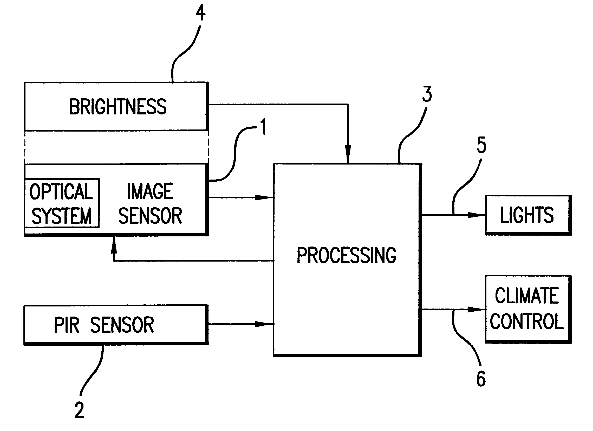
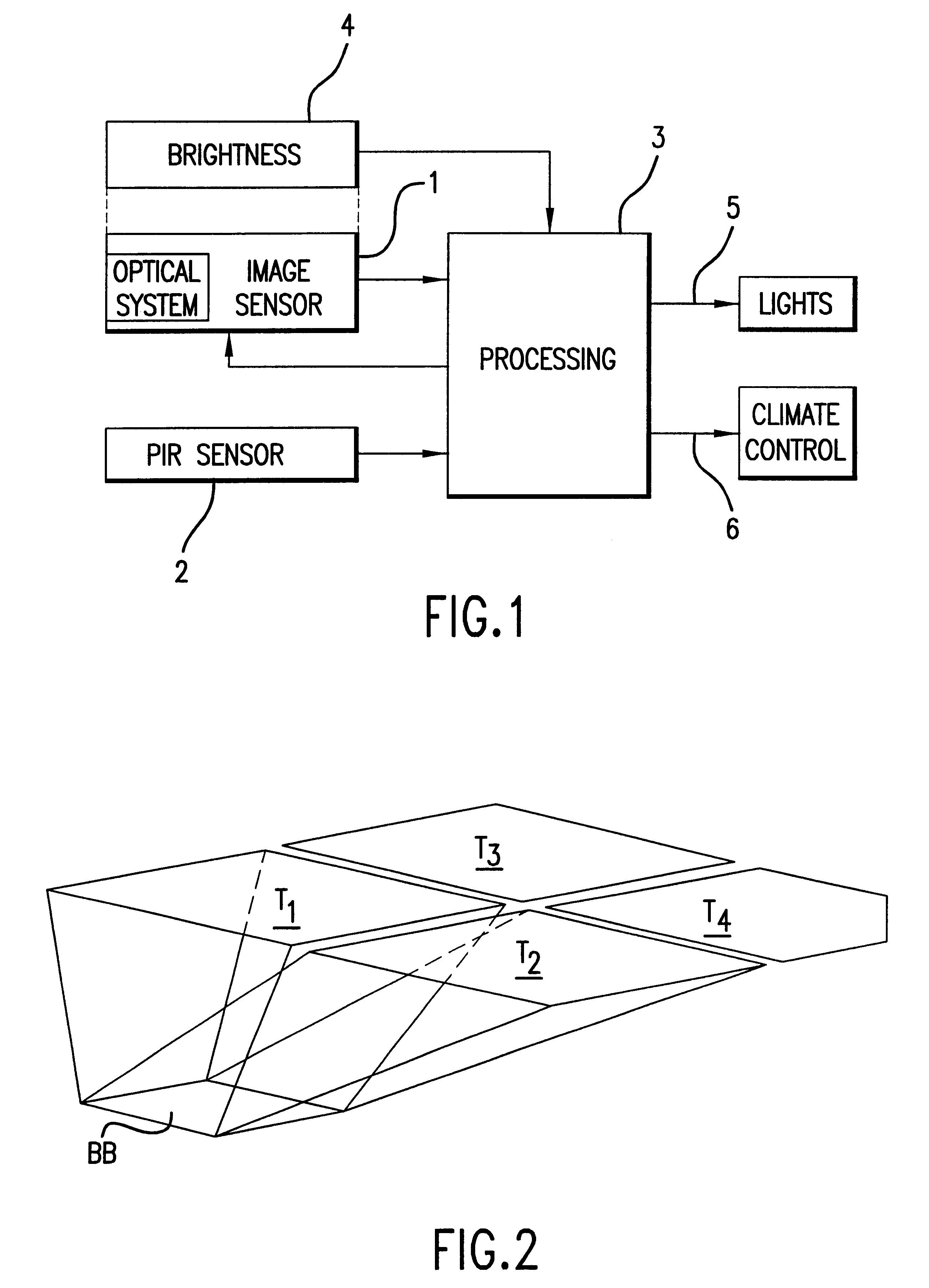
The presence detector illustrated in FIG. 1 substantially consists of an image sensor 1 operating in the visible spectral range, a passive infrared sensor 2 and, connected to these, an electronic evaluator 3 for controlling the sensors and for processing and evaluating the sensor signals. The image sensor 1 is equipped with a brightness sensor 4 such as a photo-diode for measuring the ambient brightness, which is likewise connected to the electronic evaluator 3. Alternatively, the image sensor 1 can be designed to measure the ambient brightness, whereby it measures a value for the brightness of the pixels in its visual range by means of the known integration time. This value can be the average value or a histogram or the maximum value of the brightness of the pixels, for example.

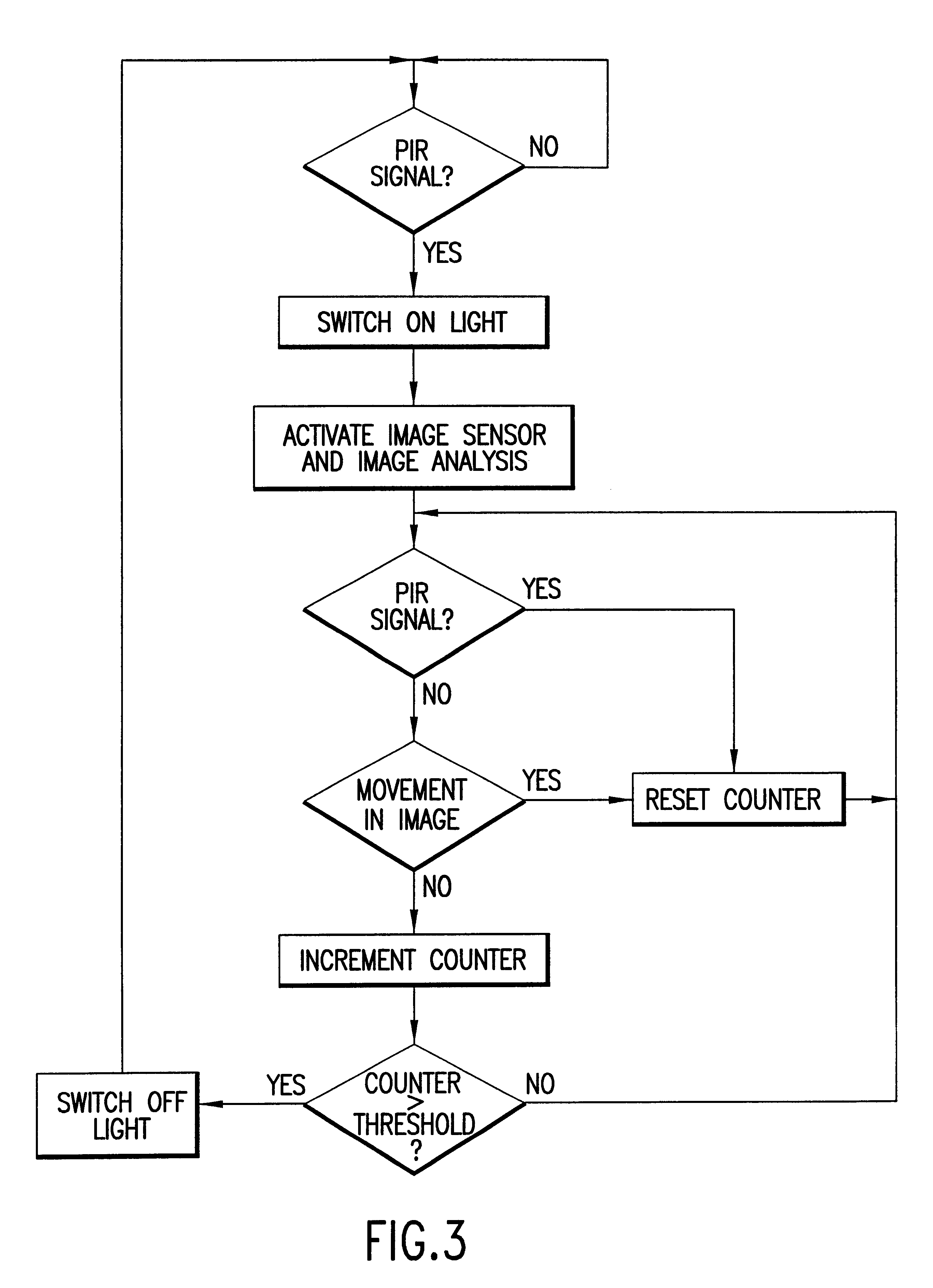
The presence detector is intended to determine the presence of persons in a room and, based on the result of this monitoring, to control the lighting of the room, as well as its heating / ventilation / air-condi...


PUM


Abstract

The presence detector has a passive infrared sensor for detecting the presence of persons in a room, an image sensor operating in the visible spectral range and an electronic evaluator for the evaluation of signals from these sensors. The signal from the passive infrared sensor is used to actuate the image sensor and, if necessary, to switch on the room lighting. Once activated, the image sensor is used to detect both movement and occupancy of a space being monitored. Application of the presence detector for the "on-demand" activation and / or control of conditioning facilities of a room, wherein the signals of both sensors are used for the control of the conditioning facility.

Description

1. Field of the InventionThe present invention relates generally to a presence detector having a passive infrared sensor for detecting the presence of stationary persons in a room.2. Description of the Related ArtIn modem presence detectors, the passive infrared sensor is equipped with a pyro-sensor for detecting thermal radiation and a structure for focusing the thermal radiation from the room being monitored, which impinges upon the pyro-sensor. The signal of the pyro-sensor detects movements of heat sources which differ from the ambient temperature in the room being monitored (see EP-A-0 303 913, for example). Today, such passive infrared sensors are obtainable in many versions and at favorable prices. However, conventional infrared sensors are either unable, or poorly able, to detect stationary persons working, for example, at a PC. Therefore, passive infrared sensors have only limited use in presence detectors in an office environment. Furthermore, it is not possible to determi...

Claims


Application Information

Patent Timeline
Patent Type & Authority Patents(United States)
IPC IPC(8): G08B13/194G08B13/196
CPCG08B13/19697
Inventor MAHLER, HANSJURGRECHSTEINER, MARTINABRACH, ROLF
Owner SIEMENS BUILDING TECH CERBERUS DIV
Why Eureka
Try Eureka