Optical fiber cable inlet device

a technology of optical fiber cable and inlet device, which is applied in the direction of electric cable installation, fibre mechanical structure, instruments, etc., can solve the problems of difficult access to the inside of the container, inconvenient use, and inconvenient us

Inactive Publication Date: 2002-11-26
CORNING RES & DEV CORP
View PDF1 Cites 102 Cited by
  • Summary
  • Abstract
  • Description
  • Claims
  • Application Information

AI Technical Summary

Benefits of technology

The invention can be well understood, and its various advantages and characteristics appear more clearly from the following description of a non-limiting embodiment given with reference to the accompanying diagrammatic drawings, in which:

Problems solved by technology

Such known cable inlet devices suffer from the drawbacks of being quite voluminous in the longitudinal direction, and of being awkward to use because it is necessary to act positively in the container to fix the securing solepiece therein by means of screws, while access to the inside of the container is often difficult.
As a result, such a cable inlet device is not very reliable because the sealing device is not always designed to be capable of withstanding external stresses for very long.

Method used


Image

  • Optical fiber cable inlet device
  • Optical fiber cable inlet device
  • Optical fiber cable inlet device

Examples


Embodiment Construction

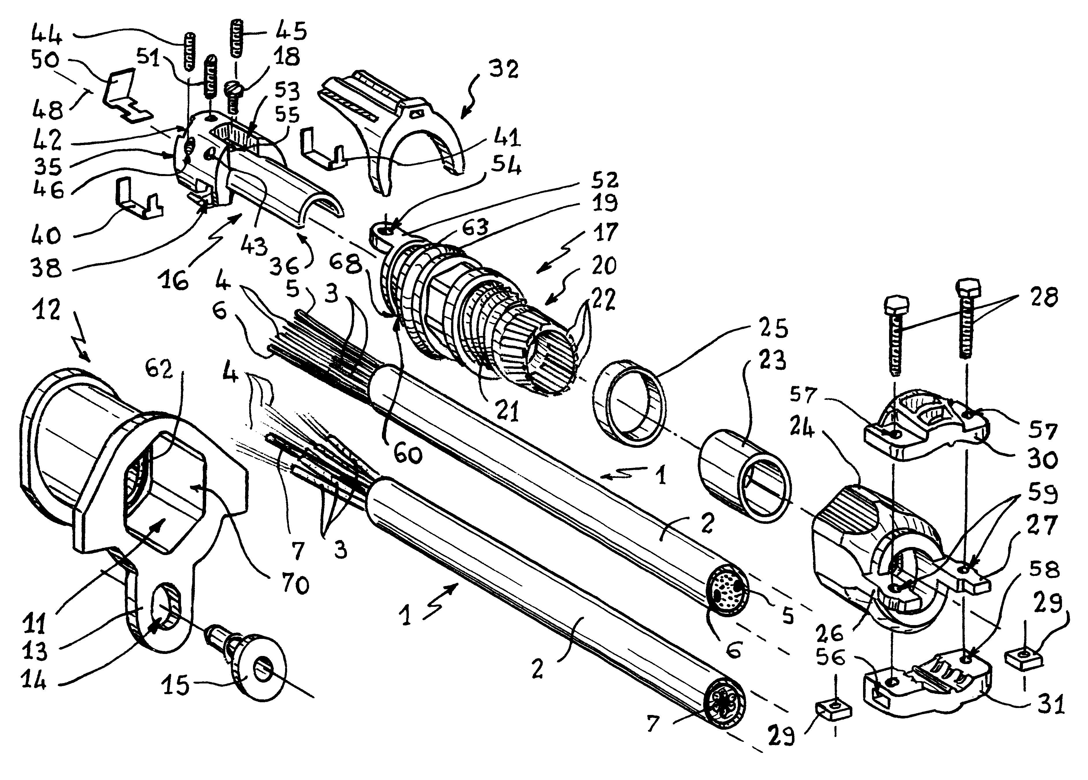
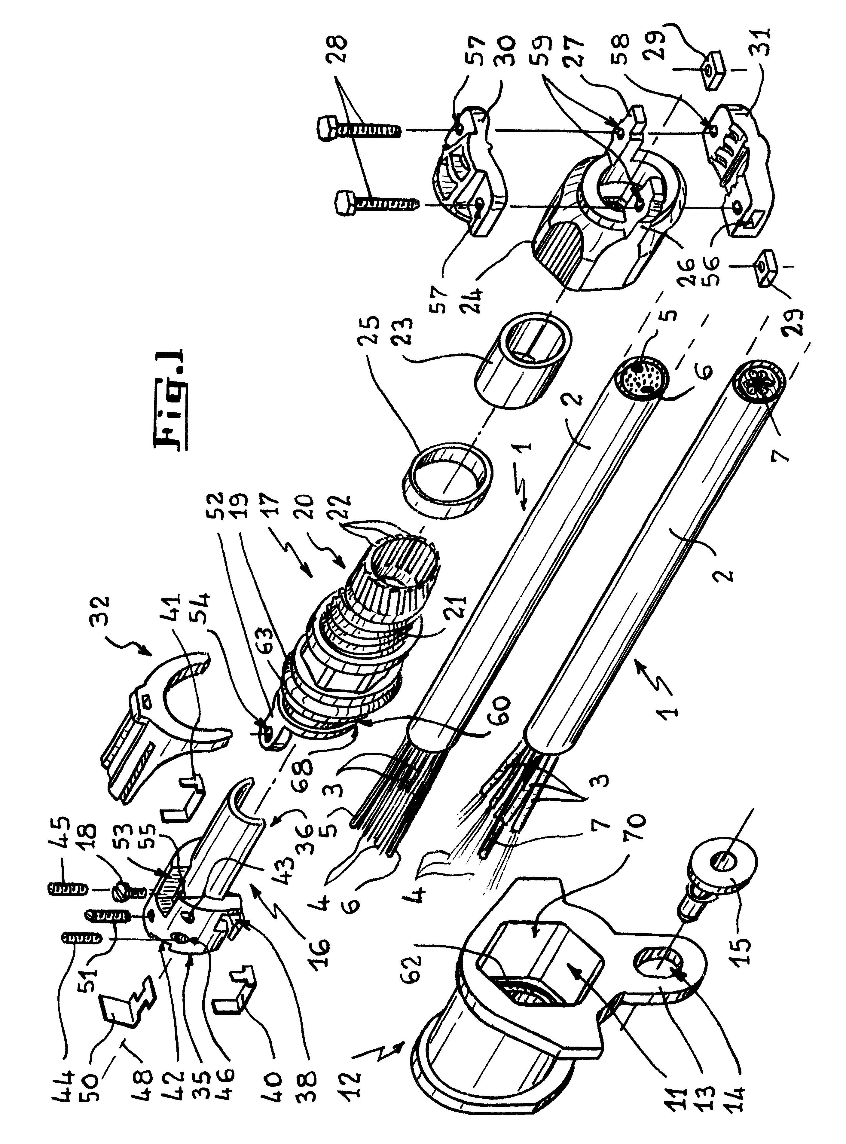
Reference is made firstly to FIGS. 1, 9A, and 10 which show the make-up of this optical cable inlet device.

In this example, the optical cable inlet device is assumed to constitute an inlet for inserting an optical cable into a splice box 8 made up of a recessed bottom 81 and of a lid 82, the bottom and the lid closing on each other with a peripheral sealing gasket 10 being interposed in conventional manner.

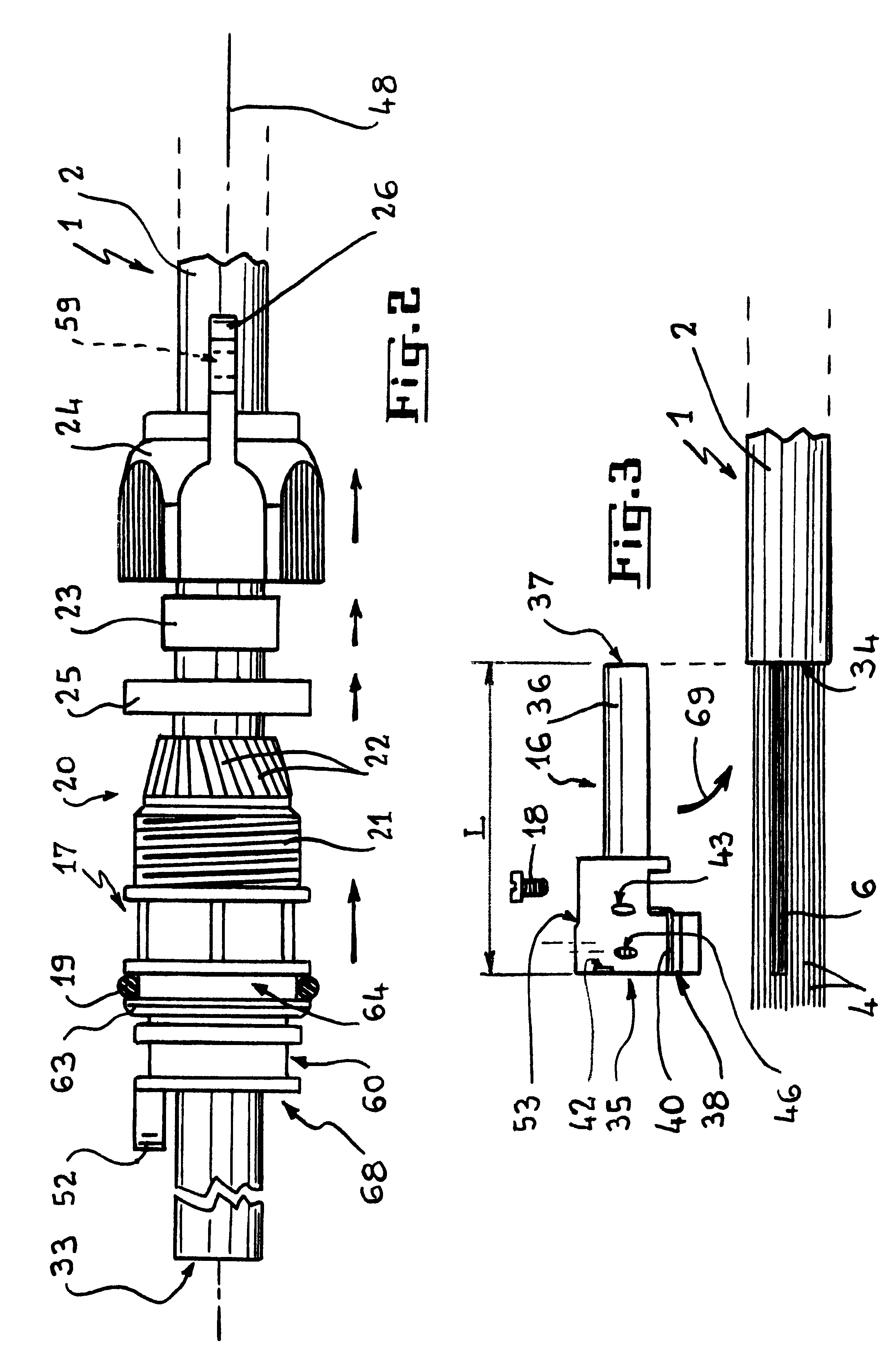
As explained below, since the inlet passageway 11 must have a special shape, while the box is a standard box, an adapter piece 12 is provided in this example. The adapter piece is placed in the standard inlet orifice 67 of the box 8 with a gasket 10 being interposed, the gasket being locally annular where it is interposed. The piece 12 is advantageously provided with a side lug 13 provided with an orifice 14 through which a screw 15 or a holding stud or any other device, can pass, thereby enabling the piece to be fixed in position on the box 8.

A metal securing solepiece 16 is situ...


PUM


Abstract

A watertight inlet device for inserting a cable containing optical fibers into a chamber or a container, e.g. into a splice box. The device includes a metal solepiece for securing the strength members of the optical cable, and which plugs into and fixes to a tubular sealing body equipped with an external O-ring gasket and having its rear portion shaped to form a sealing stuffing box on the outer sheath of the cable. The rear of the nut of the stuffing box receives a clamp for retaining the cable. Once the device has been fitted, the resulting assembly is inserted into the inlet passageway until it abuts against a shoulder in the passageway. Then only the head of the securing solepiece and a groove in the body project inside the container, the groove then receiving a key or fork for retaining the assembly.

Description

The present invention relates to a cable inlet device for inserting an optical fiber cable into a chamber or into a container, e.g. into a splice box containing an optical organizer and designed to be placed outdoors or in a buried duct.In accompanying FIG. 1, which is described in more detail further on below, reference 1 designates an optical cable of known type.That cable 1 is provided with a strong semi-rigid outer sheath 2 which protects a set of small flexible tubes 3, each of which contains a few optical fibers 4 themselves often embedded in a protective and sealing grease.In addition, two semi-rigid strength members 5 and 6, e.g. made of aramid fibers, are provided inside the sheath 2, and they are referred to as "peripheral strength members" because they are positioned close to the sheath 2 on either side of the middle longitudinal axis of the optical cable 1.The free end of the cable 1 is stripped, i.e. the sheath 2, the small protective tubes, and the sealing grease are r...

Claims


Application Information

Patent Timeline
Patent Type & Authority Patents(United States)
IPC IPC(8): G02B6/44H02G15/007
CPCG02B6/4471G02B6/4477H02G3/0675H02G15/007G02B6/4427G02B6/4448
Inventor NAUDIN, THIERRYCORBILLE, CHRISTOPHEBRUNET, HERVESALAUN, JACQUES
Owner CORNING RES & DEV CORP
Why Eureka
Try Eureka