
Control cabinet

Inactive Publication Date: 2002-12-03
RITTALWERK RUDOLF LOH GMBH & CO KG
View PDF5 Cites 27 Cited by
  • Summary
  • Abstract
  • Description
  • Claims
  • Application Information

AI Technical Summary

Benefits of technology

With this design in accordance with the invention of a switchgear cabinet, the lateral wall becomes a part of the air conditioning unit, so that the cost for parts can be considerably reduced. The outer geometry of the switchgear cabinet is not changed by the installation of the air conditioning unit which, for one, offers advantages in appearance. Furthermore, it is thus possible to take limited space conditions in the surroundings of the switchgear cabinet into consideration. Because the cooling device is associated with the lateral wall it is also possible to transfer heat with the environment directly through the area of the lateral wall. This results in good efficiency of the cooling device.
In one preferred embodiment of this invention, the cabinet body has a rack of vertical profiled frame sections and horizontal depth and width struts. The intermediate wall and the lateral wall are fastened to the rack, and the width of the intermediate space extending vertically with respect to the lateral wall is equal to or less than the corresponding vertical profiled frame sections or the depth, or respectively the width struts. The air conditioning unit thus designed hardly reduces the interior of the switchgear cabinet, so that the installation space for built-in units is only slightly reduced. In particular, the vertical profiled frame sections can still be used as attachment points for built-in units.
Another embodiment of this invention is distinguished because the vertical intermediate wall has in its upper area the openings embodied as inlet openings, and the intermediate wall supports one or several fans in its lower area, which draw the air out of the intermediate space and return the air into the interior of the cabinet body. Air then flows again back into the intermediate space through the inlet openings.
In accordance with a preferred embodiment of this invention, the intermediate wall has two or more rows of openings, and the openings are arranged symmetrically with respect to a center transverse axis and a center longitudinal axis extending in a plane of the intermediate wall. For one, a simplification of mounting is thus achieved, and it is possible to achieve an even air flow and guidance in many variations by even distribution of the openings.

Problems solved by technology

Furthermore, it is thus possible to take limited space conditions in the surroundings of the switchgear cabinet into consideration.

Method used


Image

  • Control cabinet
  • Control cabinet

Examples


Embodiment Construction

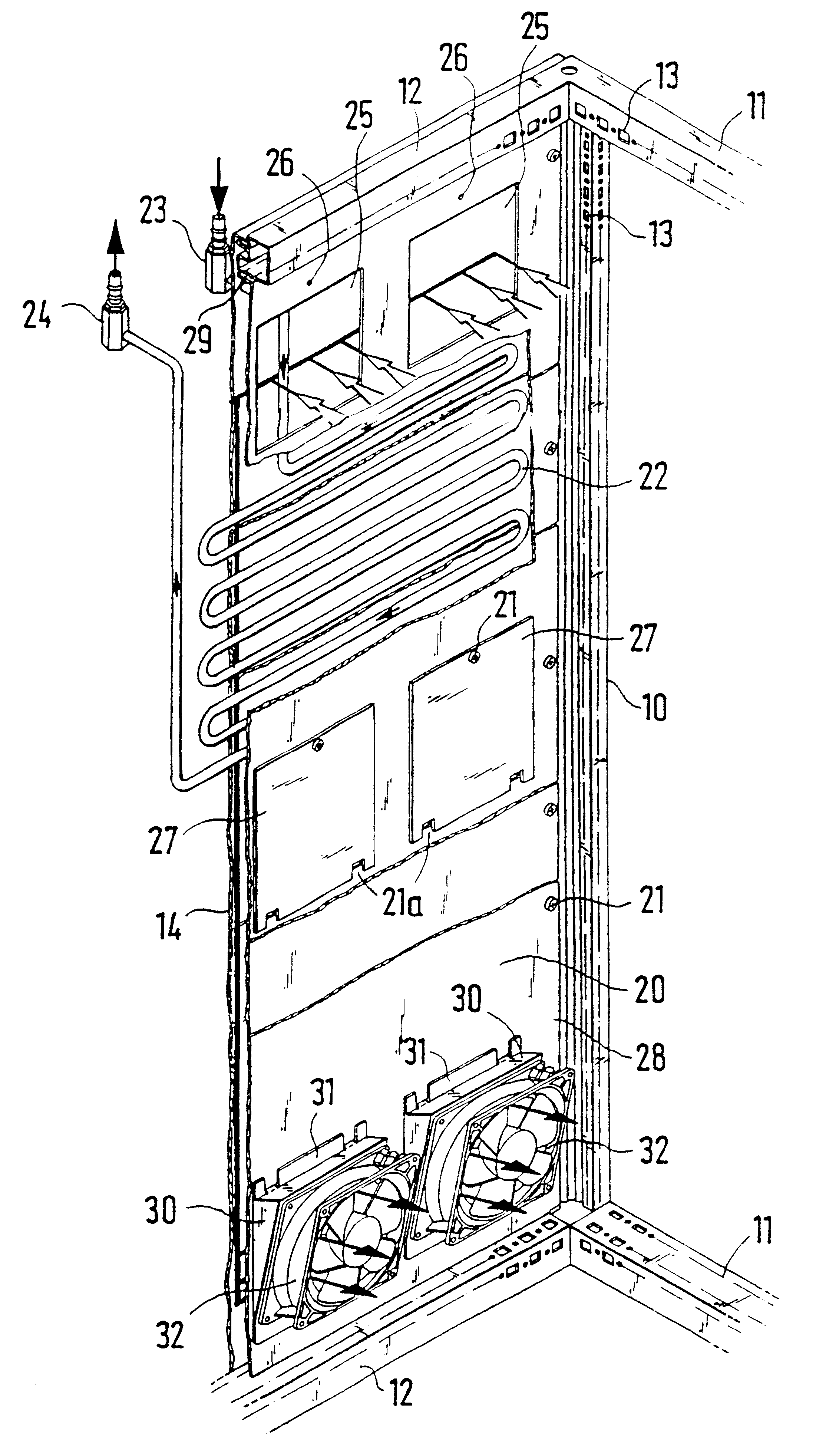
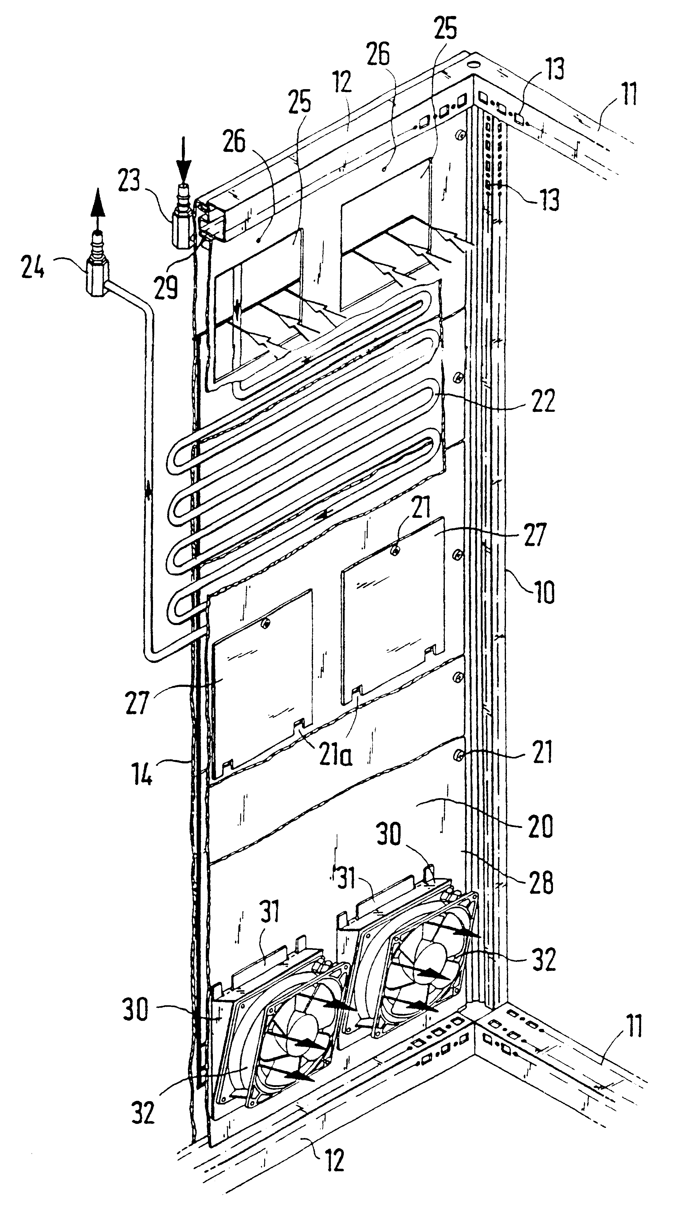
The rack has a bottom frame and a top frame with horizontal depth and width struts 11 and 12. The bottom frame is connected by means of vertical profiled frame sections 10 with the top frame. Both the vertical profiled frame sections 10 and the depth and width struts 11 and 12 have fastening receivers 13 spaced apart at even distances from each other.

The rack can be enclosed by vertical and horizontal lateral walls 14 and at least one cabinet door. The lateral wall is made of sheet steel and thus has good heat conductivity.

Only one lateral wall 14 is shown in the drawings for reasons of clarity. An intermediate wall 20 is arranged parallel with it and faces the interior of the switchgear cabinet. The intermediate wall 20 can be screwed with its vertical edges 28 to the fastening receivers 13 of the vertical profiled frame sections 28, such as with fastening screws 21. An air collection channel is formed between the lateral wall 14 and the intermediate wall 20. An air conditioning un...


PUM


Abstract

A control cabinet having a cabinet body with opened sides which can be closed at least partially by one or more side walls. An air conditioning device which is placed near at least one side wall rejects heat generated inside the cabinet body or guides it towards the inside of the cabinet body. This invention simplifies the design of the air conditioning device. For this purpose, an intermediate wall which is parallel to the side wall and located at a distance therefrom, is placed in such a way that it is oriented towards the inside of the cabinet body. In addition, the air conditioning device is placed in the intermediate space surrounded by the side wall and the intermediate wall.

Description

1. Field of the InventionThis invention relates to a switchgear cabinet with a cabinet body, a body having open sides that can be closed off at least partially by one or several lateral walls, wherein an air conditioning unit is arranged in an area of at least one lateral wall, through which heat can be removed from or supplied to the cabinet body.2. Description of Prior ArtSuch a cabinet body is known from German Patent Reference DE 41 35 894 C1. As the air conditioning unit, this switchgear cabinet has a cooling unit having fans and heat exchangers. The cooling unit is arranged in a housing, which is inserted into a cutout in a vertical lateral wall. In order to retrofit an existing switchgear cabinet with the cooling unit, it is necessary to rework the appropriate lateral wall, or respectively to install a new one.An air conditioning arrangement is known from German Patent Reference DE 43 13 022, which is installed on an exterior of the lateral wall. The lateral wall has appropri...

Claims


Application Information

Patent Timeline
IPC IPC(8): H02B1/00H02B1/56H05K7/20H02B1/30
CPCH02B1/565H05K7/20572
Inventor NICOLAI, WALTERPAWLOWSKI, ADAMSCHNEIDER, STEFAN
Owner RITTALWERK RUDOLF LOH GMBH & CO KG
Learn More