Method and system for dynamically partitioning a shared cache

a technology of shared caches and methods, applied in the field of storage hierarchy caches, can solve the problems of destructive collisions, affecting the performance of the cache, and affecting the stability of the cache,

Inactive Publication Date: 2002-12-10
IBM CORP
View PDF19 Cites 162 Cited by
  • Summary
  • Abstract
  • Description
  • Claims
  • Application Information

AI Technical Summary

Problems solved by technology

Each level of a storage hierarchy has a size and a performance penalty associated with accessing it.
Typically, levels with more storage have a higher performance penalty.
This is problematic for a shared cache when the actual partitioning of main memory occurs below the level of the cache.
That is, since processor partitions use the same addresses to refer to different memory locations, destructive collisions (e.g., logical interference) can occur in the shared cache.
Such has not been possible in the conventional systems and methods.
Once again, the conventional systems have not provided such a structure and method.
Thus, in the conventional multiprocessor system using a shared-cache memory, partitioning the multiprocessor system with the processors having separate address spaces, a problem occurs in caching the same address to different address spaces.
That is, the shared cache is unable to distinguish between multiple address spaces.
The PID tag extension does not guarantee fairness of cache storage space to the partitions, nor does it allow a partition to reserve a portion of

Method used


Image

  • Method and system for dynamically partitioning a shared cache
  • Method and system for dynamically partitioning a shared cache
  • Method and system for dynamically partitioning a shared cache

Examples


first embodiment

The first embodiment has several advantages. For example, partitions compete for storage, and the portion of the cache occupied by any given partition varies dynamically. Therefore, there is no need for a mechanism to allocate cache space to partitions.

The competition for cache lines between partitions is expected to result in a steady state occurring, where each partition has a portion of the cache proportional to its access frequency, and hence, need. The technique and cache partitioning system of the first embodiment adjusts dynamically to the cache resource needs of the partitions.

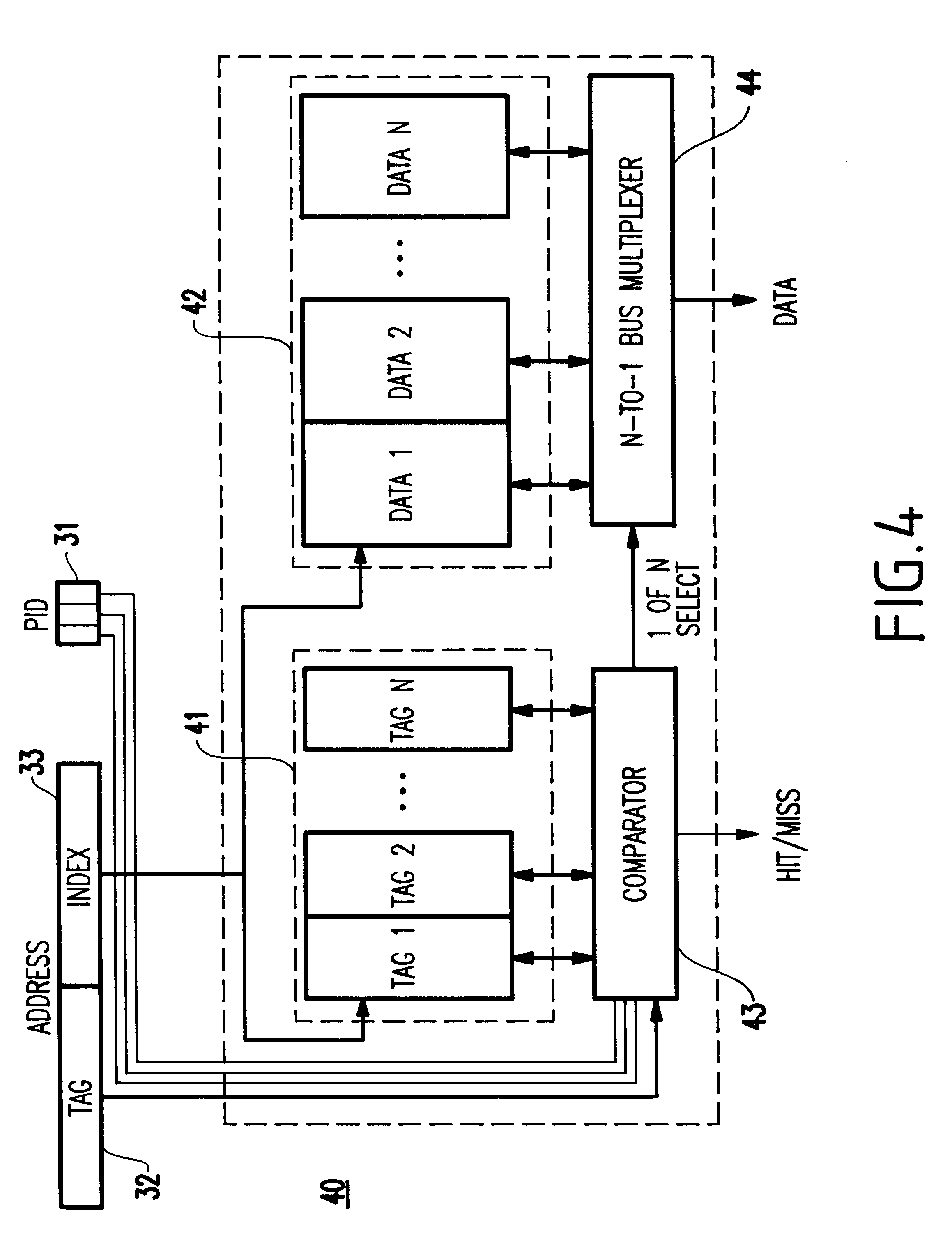
Additionally, the first embodiment has a negligible impact on cache performance because the only significant addition to the conventional cache implementation is a minor extension in the width of the tag comparators.

However, a drawback of the first embodiment of the present invention is that there is no guaranteed "fairness" of cache storage space to the partitions, nor does it allow a partition to res...

second embodiment

The second embodiment was designed to overcome several of the above-mentioned drawbacks of the first embodiment. Quite simply, the second embodiment assigns "guaranteed space" to predetermined ones of the partitions.

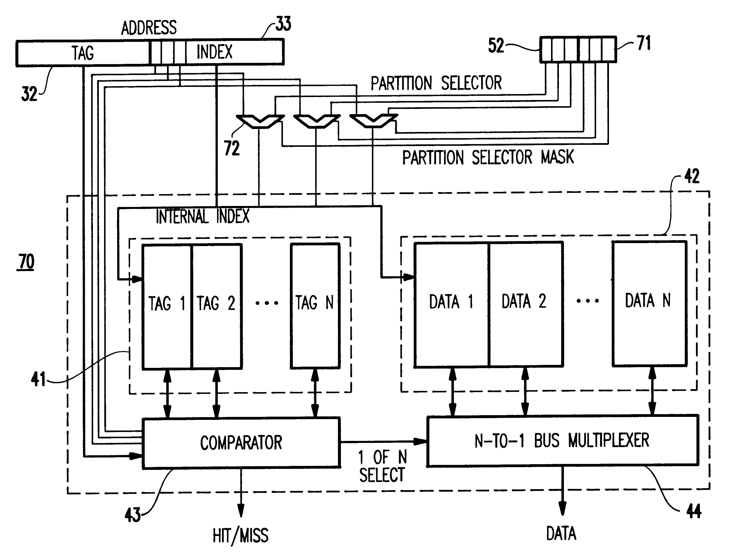
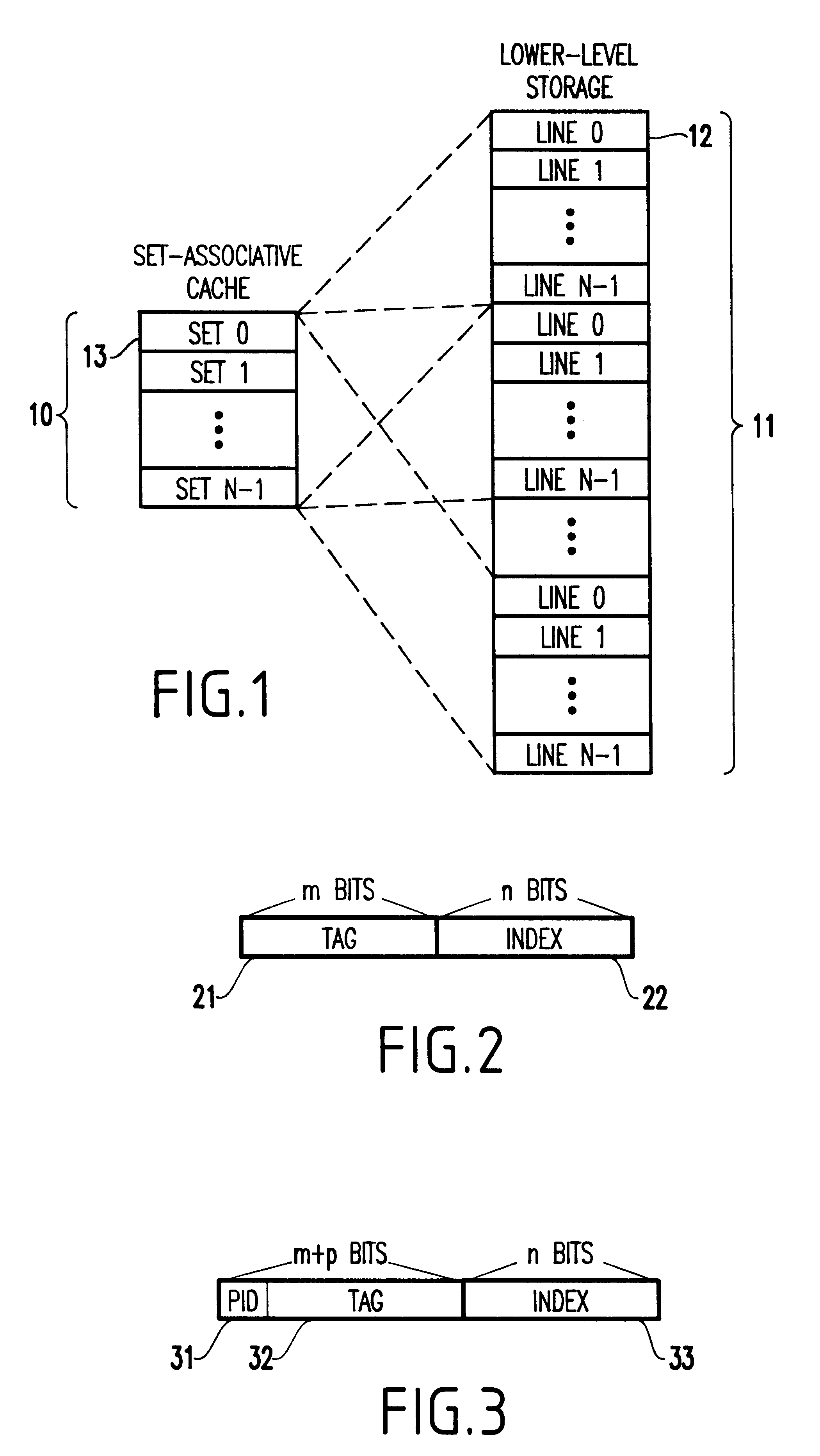
In the second embodiment of the invention, as shown by FIGS. 5-7, the index sets of the cache are partitioned into disjoint groups, or "cache partitions" of various sizes, and each partition is allocated a unique cache partition with a size that meets its needs.

Furthermore, the sizes of the cache partitions can be varied dynamically to adjust to resource needs.

In the second embodiment, cache partitioning is accomplished by forcing (e.g., constraining) some of the index bits in the address presented to the cache to particular values based upon the partition performing the reference. This "constraining" has the effect of restricting the index to a subset of the total sets in the cache.

FIG. 5 illustrates how a cache address is manipulated by the second embodiment to provide...


PUM


Abstract

A cache memory shared among a plurality of separate, disjoint entities each having a disjoint address space, includes a cache segregator for dynamically segregating a storage space allocated to each entity of the entities such that no interference occurs with respective ones of the entities. A multiprocessor system including the cache memory, a method and a signal bearing medium for storing a program embodying the method also are provided.

Description

1. Field of the InventionThe present invention generally relates to caching in a storage hierarchy, and more particularly to a method and system for dynamic allocation of disjoint storage spaces in a shared cache.2. Description of the Related ArtCaches are used within storage hierarchies to reduce access latencies. Each level of a storage hierarchy has a size and a performance penalty associated with accessing it. Typically, levels with more storage have a higher performance penalty. For example, the traditional memory storage hierarchy of a computer (excluding caches) consists of a small number of processor registers, solid state memory, magnetic disks, and magnetic tapes.Caches can be inserted into a storage hierarchy to improve performance by taking advantage of locality of reference. A cache has a lower performance penalty than the storage layers below it, and it stores the most recently referenced items from the hierarchy below.FIG. 1 shows how a set-associative cache 10 maps r...

Claims


Application Information

Patent Timeline
IPC IPC(8): G06F12/08
CPCG06F12/084G06F12/0842G06F12/0848G06F12/0864G06F2212/2542G06F12/08
Inventor BLUMRICH, MATTHIAS AUGUSTIN
Owner IBM CORP
Why Eureka
Try Eureka