Chemical treating apparatus and flow rate controlling method thereof

a flow rate and flow control technology, applied in the direction of cleaning processes, cleaning using liquids, instruments, etc., can solve the problems of loss of treatment efficiency, inability to control inability to continuously change the amount of discharge,

Inactive Publication Date: 2002-12-17
SONY CORP
View PDF8 Cites 1 Cited by
  • Summary
  • Abstract
  • Description
  • Claims
  • Application Information

AI Technical Summary

Problems solved by technology

In such a conventional method, it is hard to allow the amount of discharge to be continuously variable and to control the amount of discharge according to the amount or variation of amount of the liquid treating chemical supplied from the outer bath.
Specifically, since it

Method used


Image

  • Chemical treating apparatus and flow rate controlling method thereof
  • Chemical treating apparatus and flow rate controlling method thereof
  • Chemical treating apparatus and flow rate controlling method thereof

Examples


Embodiment Construction

Preferred embodiments of this invention will be described with reference to the accompanying drawings:

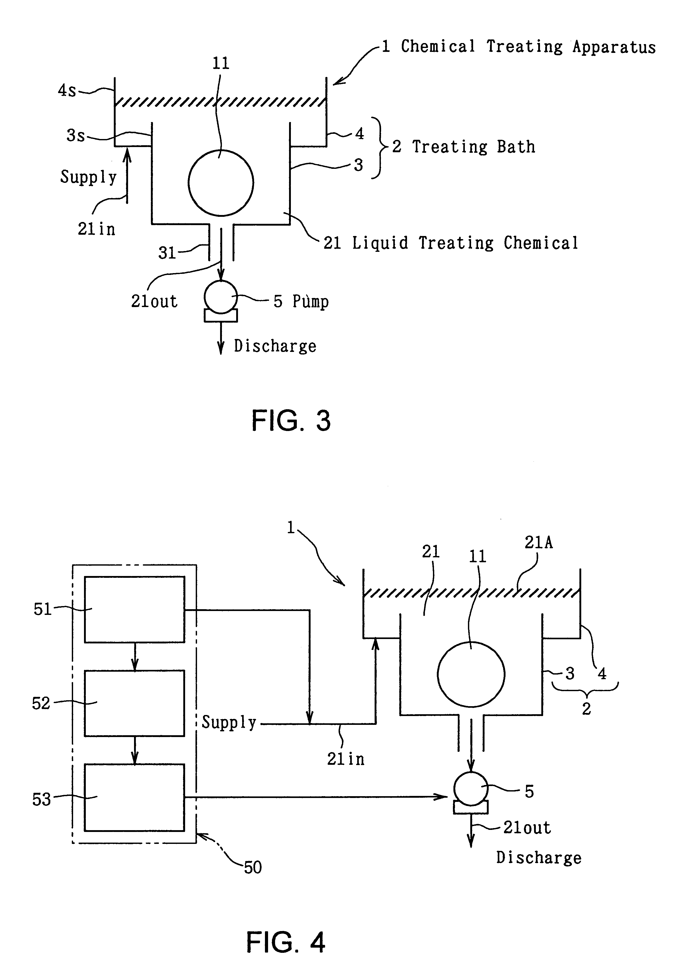
One example in an embodiment of the chemical treating apparatus of the present invention will be described with reference to the schematic block diagram of FIG. 3.

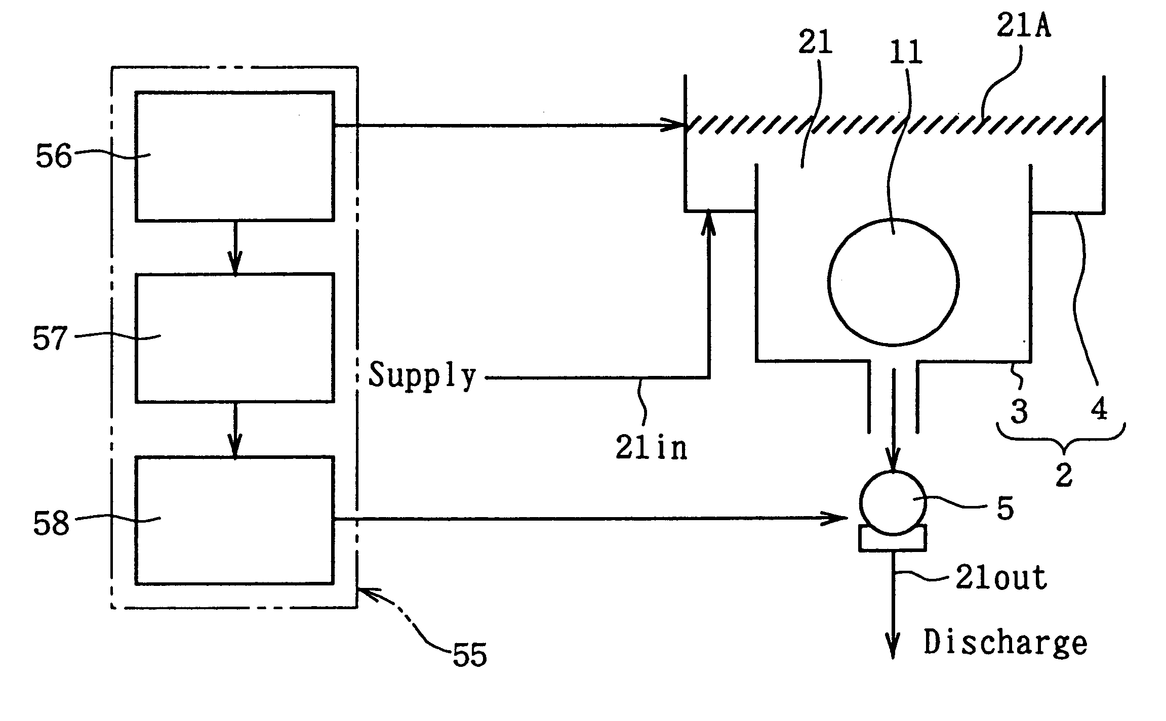
As shown in FIG. 3, a chemical treating apparatus 1 is a down-flow type chemical treating apparatus in which a liquid treating chemical (liquid chemical) 21in (shown by an arrow) is supplied from the outside of a treating bath 2 while the liquid treating chemical 21out is discharged from the bottom portion of the treating bath 2. This chemical treating apparatus 1 can be, for example, either a cleaning apparatus or a wet etching apparatus depending on the type of liquid treating chemical 21. The above-mentioned treating bath 2 consists of a main bath 3 storing the subject of treatment (for example, a semiconductor wafer, a glass wafer, etc.) 11 subjected to liquid chemical treatment and an outer bath 4 being the supplying ...


PUM


Abstract

When trying to keep the amount of a liquid treating chemical in a treating bath constant by discharging almost the same amount of the liquid treating chemical as the liquid treating chemical supplied, the flow of the liquid treating chemical in the treating bath fell into disorder, which made it hard to keep the flow of the liquid treating chemical in the treating bath in the laminar state.A down-flow type chemical treating apparatus 1 in which a liquid treating chemical 21 is supplied from the outside of a treating bath 2 (main bath 3) while the liquid treating chemical 21 is discharged from the bottom portion of the treating bath 2 (main bath 3), comprising a pump 5 on the chemical discharging side of the main bath 3 which consists of a rotary pump allowing to discharge the liquid treating chemical 21 to the outside of the main bath 3 keeping the flow of the liquid treating chemical 21 substantially in the main bath 3 almost in the laminar state.

Description

1. Field of the InventionThis invention relates to a chemical treating apparatus and a flow rate controlling method thereof, particularly to a chemical treating apparatus used in the manufacturing process of semiconductor devices, especially in the cleaning process, and a flow rate controlling method thereof.2. Description of the Prior ArtAs it will be stated below, there are two methods for treating (cleaning, etching, etc.) the face surface or the back surface of a substrate such as a semiconductor substrate, a quartz substrate, and the like.(a) One method of chemical treatment is using an overflow type chemical treating apparatus 101, as shown in FIG. 1, in which the subject of treatment (for example, semiconductor wafer, glass wafer, etc.) 131 is placed in a main bath 111, and a liquid treating chemical 121in (shown by an arrow) is supplied to the main bath 111 from its bottom portion while the liquid treating chemical 121out (shown by an arrow) in the main bath 111 is discharge...

Claims


Application Information

Patent Timeline
IPC IPC(8): B08B3/10G05D7/06H01L21/00H01L21/306H01L21/304
CPCB08B3/10G05D7/0676H01L21/67057H01L21/67086Y10S134/902H01L21/302
Inventor MAKITA, MASAHIRONISHIZAKI, MITSUHIRO
Owner SONY CORP
Why Eureka
Try Eureka