Sonic energy process chamber

a process chamber and sonic energy technology, applied in the direction of optical radiation measurement, cleaning using liquids, instruments, etc., can solve the problems of increasing manufacturing costs, existing machines, and relatively large consumption of process chemicals and water

Inactive Publication Date: 2008-03-04
APPLIED MATERIALS INC
View PDF16 Cites 4 Cited by
  • Summary
  • Abstract
  • Description
  • Claims
  • Application Information

AI Technical Summary

Benefits of technology

[0010]A semiconductor processing chamber and methods in treating workpieces have been invented that provide a uniform distribution of sonic energy to achieve a uniform process treatment across substantially the entire wafer surface being treated. Specifically, after much research and development, it has been determined that by providing a sonic energy source with a large enough total surface area relative to the surface area of the workpiece to be treated, one can sufficiently reduce the boundary layer thickness between the workpiece and the processing fluid to provide a more uniform and efficient treatment across substantially the entire surface of the workpiece being treated.
[0011]The present invention also reduces the dampening effect present in prior process chambers and improves liquid flow in the process chamber to expedite processing and provide more efficient overall processing. Particularly, it has been determined that by positioning the workpiece at an angle to the sonic energy source, the sonic energy is provided with a natural outlet or flow path. That is, instead of continuing to reverberate off the workpiece and the sonic energy source, sonic energy introduced into the fluid will eventually be channeled out from between the source and the workpiece, reducing interference and lessening any dampening effect. As a result, the efficiency of the process is greatly enhanced. Moreover, an angled sonic energy source improves fluid flow distribution across the workpiece surface and improves the ability to quickly and adequately drain fluid from the process chamber.
[0012]Accordingly, the sonic energy process chamber of the present invention provides remarkably improved semiconductor manufacturing processes that result in more consistent, uniform microelectronic devices, better manufacturing yields and lower manufacturing costs.
[0014]In another embodiment of the present invention, a workpiece processor includes a bowl, a sonic-energy source and a process head. Processing fluids are introduced into the bowl and distributed across the surface of the workpiece in the processor. The sonic energy source is positioned within the bowl and introduces sonic energy into the processing fluid. A process head holds the workpiece and lowers the workpiece into the processing fluid for treatment. The sonic energy source has a total surface area that is large enough relative to the surface area of the workpiece to be treated such that the boundary layer between the processing fluid and the workpiece is sufficiently reduced to provide a uniform process treatment across substantially the entire treated surface area of the workpiece.
[0018]In another embodiment of the present invention, the sonic energy supplied to the process chamber is monitored and controlled to prevent the sonic energy from destroying or damaging the workpiece.

Problems solved by technology

However, existing machines have several disadvantages.
These disadvantages include relatively large consumption of process chemicals and water.
This consumption of process chemicals increases manufacturing costs, which ultimately increases the cost of the final product, such as e.g., computers, cell phones, and virtually all types of consumer, industrial, commercial and military electronic products.
In addition, many process chemicals are toxic and require special handling, storage, and disposal methods.
These can be costly and difficult, but are necessary for health, safety and environmental reasons.
Existing machines often are not able to sufficiently uniformly apply process chemicals.
This can result in lower yields.
This inefficient use of process chemicals leads to the disadvantages described above.
Manufacturing semiconductor and similar products on a commercial scale requires a fab or manufacturing facility often costing hundreds of million dollars to build and equip.
Operating and maintenance costs are also very high.
While conventional processing with liquids may produce the desired results, it can be time consuming.
Further, the higher the level of sonic energy used, the greater likelihood there is of dislodging particles and impurities that could get lodged in the minute crevices created by the microelectronics formed on the wafer surface.
Too much sonic energy, however, and the microelectronics, the wafer itself, and any dielectric on the wafer surface could be destroyed.
Thus, a problem exists in the semiconductor processing industry of balancing the benefits of using sonic energy, without damaging the wafers and microelectronics.
As a result, it is difficult to achieve a uniform process treatment across the entire surface of the wafer.
Moreover, the configuration of the sonic energy sources disclosed in U.S. Pat. Nos. 6,492,284 and 6,511,914: (1) create a dampening effect by trapping the sonic energy between the source and the wafer, reducing the effectiveness of the sonic energy; and (2) make it difficult to adequately drain chemistry or liquid from the bowl.

Method used


Image

  • Sonic energy process chamber
  • Sonic energy process chamber
  • Sonic energy process chamber

Examples


Embodiment Construction

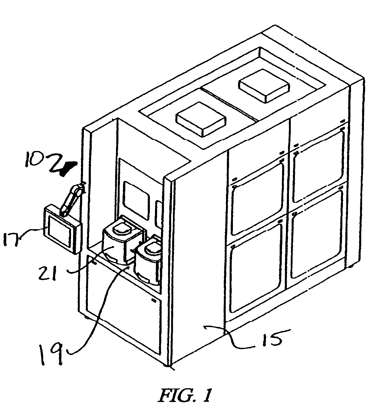
[0031]As shown in FIG. 1, a processing system 10 has an enclosure 15, a control / display 17, and an input / output station 19. Wafers or workpieces 24 within pods or boxes 21 (e.g., FOUPs) are removed from the boxes 21 at the input / output station 19 and processed within the system 10.

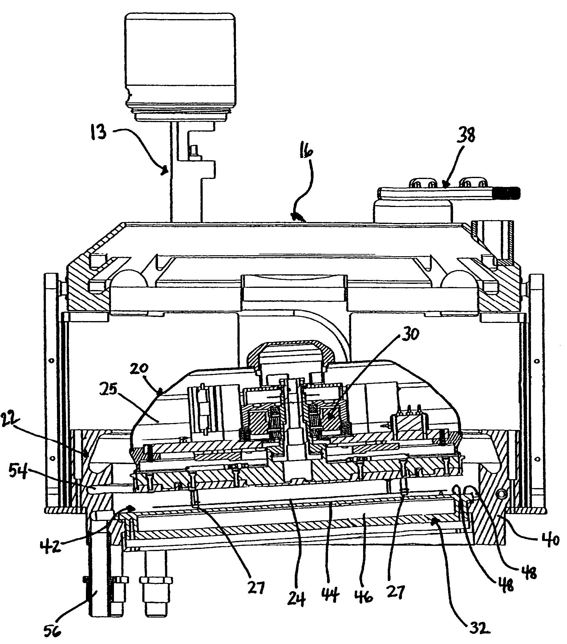
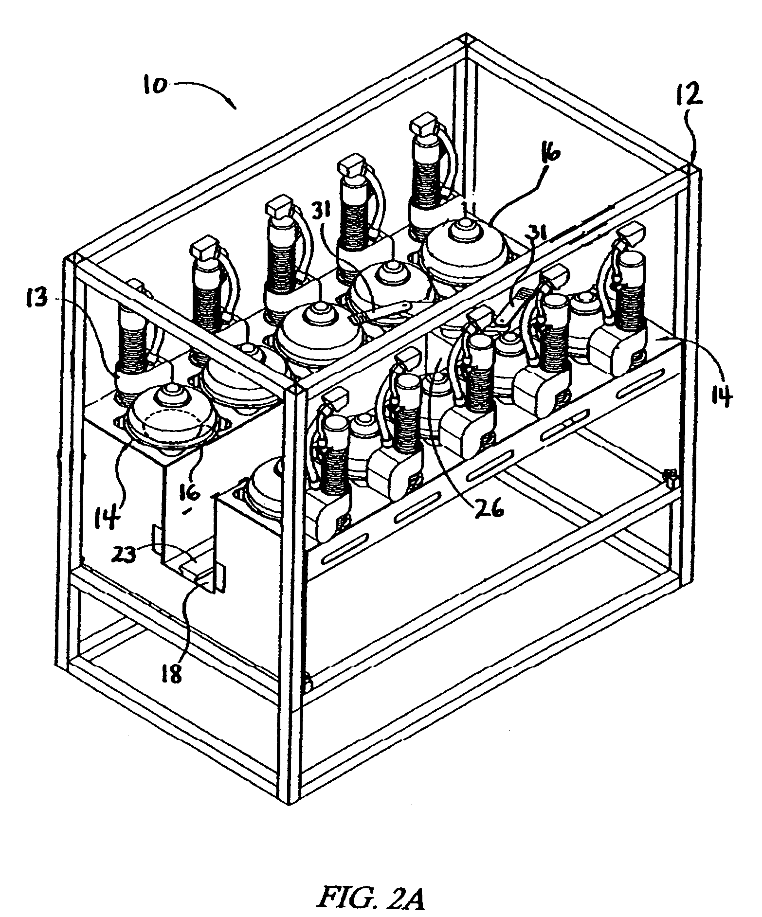
[0032]Turning to FIGS. 2A and 2B, the processing system 10 includes a support structure frame 12 with a plurality of processing stations 14 within the enclosure 15. A processing station 14 includes a process chamber 16 and a lift / rotate actuator 13. The process chamber 16 may be configured to process workpieces 24, such as 200 or 300 mm diameter semiconductor wafers provided within sealed boxes 21, open cassettes, or other carrier or container. The workpiece process chamber 16 of the present invention is designed to be utilized in a processing system 10, for example, as disclosed in pending U.S. patent application Ser. Nos. 10 / 733,807 filed Dec. 11, 2003 and Published as U.S. Appication Publication 2004 / 02...


PUM

PropertyMeasurementUnit
angleaaaaaaaaaa
angleaaaaaaaaaa
angleaaaaaaaaaa

Abstract

A system for processing a workpiece includes a base having a bowl or recess for holding a processing fluid. A sonic energy source, such as a megasonic transducer, provides sonic energy into a processing fluid in the bowl. A process head holds a workpiece. A process head lifter lowers the head holding the workpiece into the processing fluid in the bowl. Sonic energy is provided to the workpiece through the processing fluid, optionally while the processing head spins the workpiece. The processing fluid may include de-ionized water and an etchant.

Description

CROSS-REFERENCE TO RELATED APPLICATIONS[0001]This application claims priority from provisional U.S. Patent Application No. 60 / 552,987, filed Mar. 12, 2004. Priority to this application is claimed under 35 U.S.C. § 119, and the disclosure of this application is incorporated herein by reference in its entirety.TECHNICAL FIELD[0002]The invention relates to surface preparation, cleaning, rinsing and drying of workpieces, such as semiconductor wafers, flat panel displays, rigid disk or optical media, thin film heads or other workpieces formed from a substrate on which microelectronic circuits, data storage elements or layers, or micro-mechanical elements may be formed. These and similar articles are collectively referred to herein as a “wafer” or “workpiece.” Specifically, the present invention relates to a sonic energy process chamber and the use of sonic energy to treat semiconductor workpieces.BACKGROUND OF THE INVENTION[0003]The semiconductor manufacturing industry is constantly seek...

Claims


Application Information

Patent Timeline
Patent Type & Authority Patents(United States)
IPC IPC(8): B08B3/12G01N29/04
CPCH01L21/67028H01L21/67086H01L21/6719Y10S134/902
Inventor WIRTH, PAUL Z.SCRANTON, DANA R.AEGERTER, BRIAN
Owner APPLIED MATERIALS INC
Why Eureka
Try Eureka