Substrate disposal device

A substrate processing device and substrate technology, applied in lighting and heating equipment, applications, cleaning methods and appliances, etc., can solve the problems of metal film damage, ice particles and uneven impact energy on the substrate surface, and achieve efficient cleaning effect

Inactive Publication Date: 2006-09-27
DAINIPPON SCREEN MTG CO LTD
View PDF0 Cites 8 Cited by
  • Summary
  • Abstract
  • Description
  • Claims
  • Application Information

AI Technical Summary

Problems solved by technology

Therefore, there is a problem that the metal film is locally damaged due to the non-uniformity of the impact energy of the particles of ice and the surface of the substrate.

Method used


Image

  • Substrate disposal device
  • Substrate disposal device
  • Substrate disposal device

Examples


Embodiment Construction

[0031] Hereinafter, the best mode for carrying out the present invention will be described with reference to the drawings.

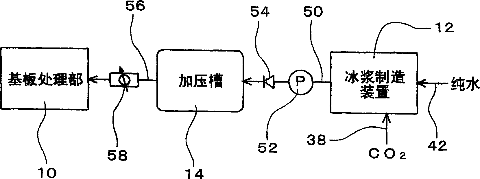
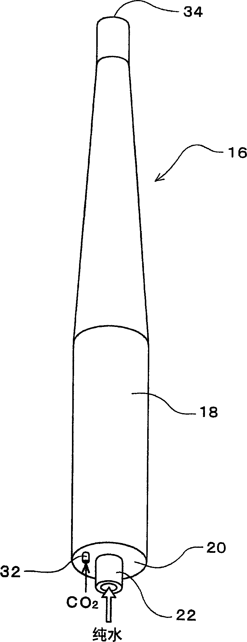
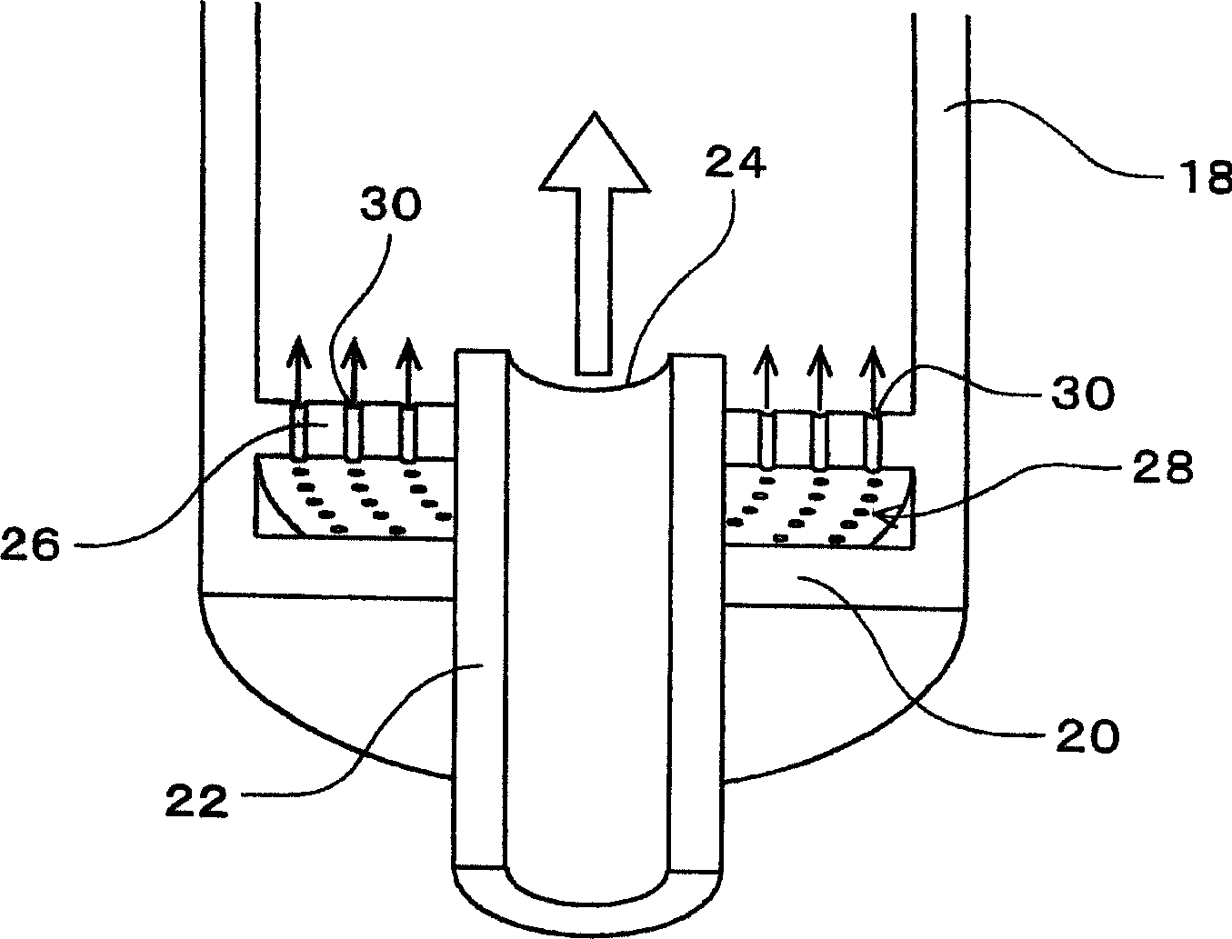
[0032] Figure 1 to Figure 5 Showing an example of an embodiment of the present invention, figure 1 It is a schematic diagram showing a substrate processing apparatus, and in this example, an overall configuration of a substrate cleaning apparatus. in addition, figure 2 It is a perspective view of the appearance of the main body of the ice slurry manufacturing apparatus, which is one of the structural elements of the substrate cleaning apparatus, image 3 It is an enlarged perspective view of a part of the state in which the main body of the ice slurry production device is cut vertically, Figure 4 is a block diagram of the ice slurry manufacturing device, Figure 5It is a schematic front view showing an example of the structure of the substrate processing unit of the substrate cleaning apparatus.

[0033] This substrate cleaning apparatus includes...


PUM


Abstract

PROBLEM TO BE SOLVED: To provide a device capable of uniformly treating without unevenness, when treating a substrate by supplying a treatment liquid containing fine ice particles onto the surface of the substrate, and not damaging a coating formed on the substrate. ŽSOLUTION: The device includes a substrate treatment unit 10 for treating the substrate, an ice slurry maker 12 causing pure water to contain fine ice particles, a means for dissolving a gas in ice slurry, a pressurizing pump 52 and a pressurizing tank 14 for pressurizing the ice slurry, and an ice slurry supply pipe 56 for supplying the pressurized ice slurry with the gas dissolved to the substrate treatment unit 10. Ž

Description

technical field [0001] The present invention relates to a treatment liquid for supplying fine particles containing ice to the main surfaces of substrates such as semiconductor wafers, glass substrates for liquid crystal display (LCD), glass substrates for plasma display (PDP), printed substrates, ceramic substrates, and electronic device substrates. Substrate processing equipment for cleaning and other processing of substrates. Background technique [0002] For example, cleaning of substrates in flat panel display (FPD) manufacturing equipment such as LCDs and PDPs is performed through a series of steps as follows: Removal of organic contamination by UV irradiation with an excimer laser → by using a roller Removal of pollutants over 1 μm by brush scrubbing → Removal of chemical solution after chemical solution cleaning by displacement cleaning → Precision cleaning by 2-fluid cleaning → Final cleaning by final water rinsing. In addition, in recent years, instead of roller br...

Claims


Application Information

Patent Timeline
Patent Type & Authority Applications(China)
IPC IPC(8): B08B7/00B08B3/04F25C1/00G02F1/13H01L21/304B08B7/02B23K1/00B23K101/40
CPCC09K3/14G02F1/1303G02F1/1316H01L21/67051
Inventor 山本悟史
Owner DAINIPPON SCREEN MTG CO LTD
Why Eureka
Try Eureka