Method and device for inspecting objects

a technology of objects and methods, applied in the direction of instruments, image data processing details, image data processing, etc., can solve the problems of prior art methods and devices, insufficient speed and high accuracy for automatic inspection of properties, and inability to meet current and future demands

Inactive Publication Date: 2002-12-17
MYDATA AUTOMATION
View PDF15 Cites 46 Cited by
  • Summary
  • Abstract
  • Description
  • Claims
  • Application Information

AI Technical Summary

Problems solved by technology

An automatic inspection of the properties is difficult to perform at high speed and high accuracy.
However, there are problems associated with prior art methods and devices.
Generally, prior art methods and devices are dedicated to a single task and often they are not fast enough to comply with current and future demands.
Drawbacks of this known apparatus are the limited use thereof.
For example, neither accurate volume measurements nor accurate area measurements are performable, at least not reasonably fast, since this would require a vast number of scans in both directions.
While this apparatus enables several types of properties to be inspected at high speed it is complex and performs only measurements of height profiles as a basis for all determinations.
The limitations to height profile measurements causes a limited accuracy.
By measuring the profiles extremely closely, a certain improvement of accuracy may be obtained, However, this requires a high speed of measurement, which is difficult to achieve.

Method used


Image

  • Method and device for inspecting objects
  • Method and device for inspecting objects
  • Method and device for inspecting objects

Examples


Embodiment Construction

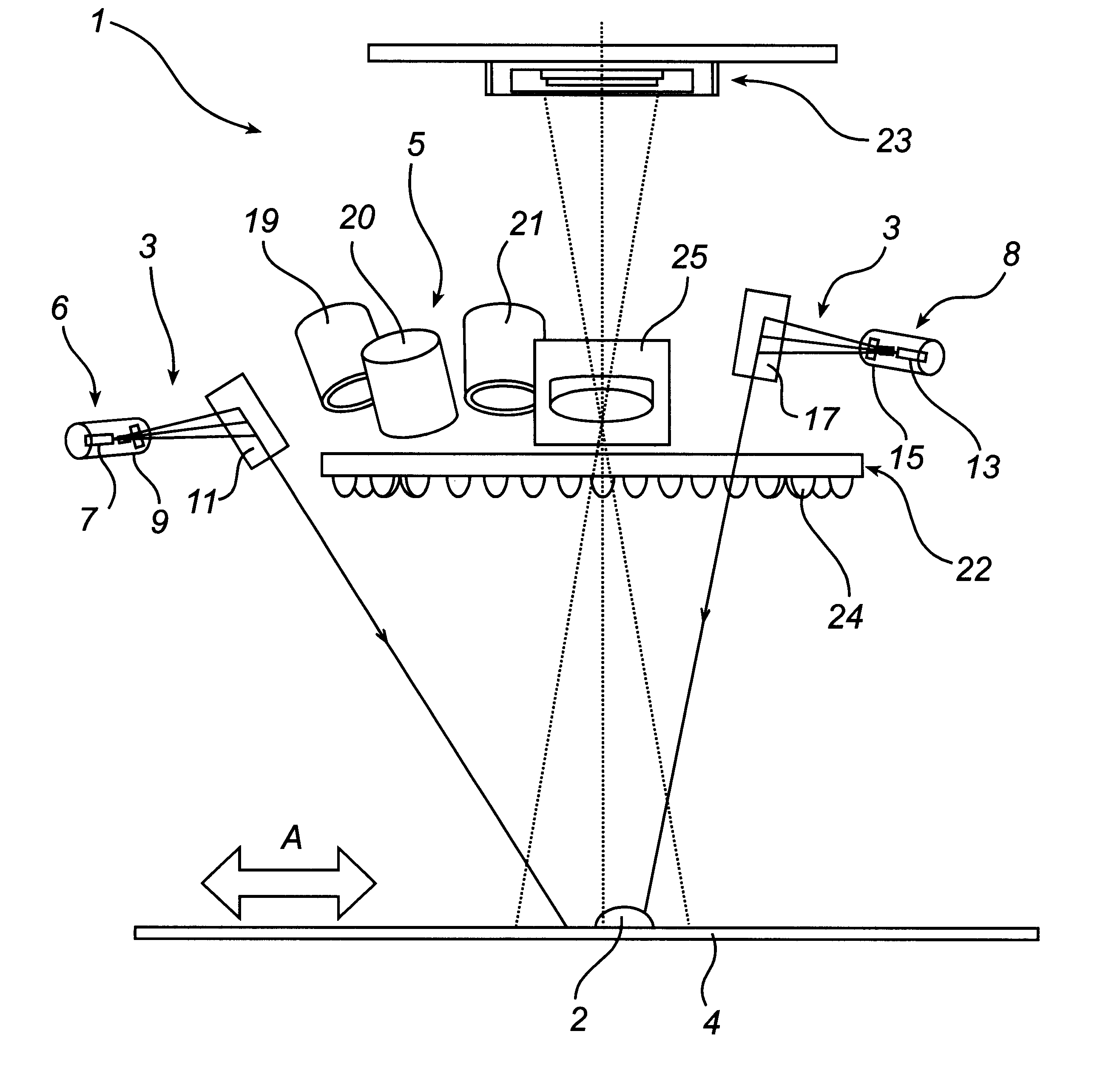
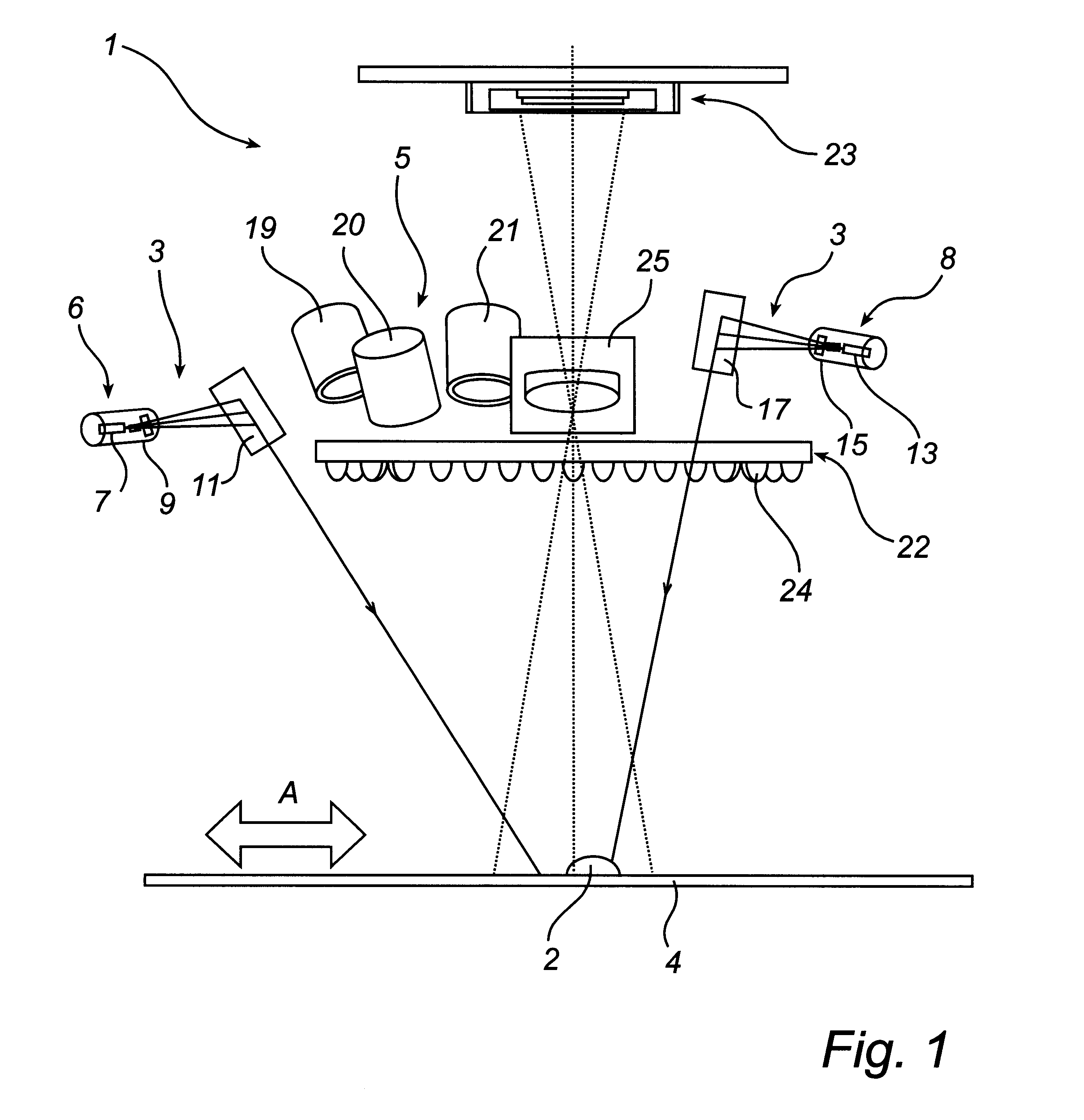
A device according to an embodiment of the present invention is shown in FIG. 1. The device 1 is arranged above a substrate carrying an object 2 to be inspected. The device 1 and the object 2 are moving mutually, i.e. relative to each other, which is indicated by an arrow A. The object 2 could be of many different kinds as mentioned above. However, for the sake of simplicity of explanation, let us in the following assume that the object 2 is a solder paste deposit, which has been dispensed on the surface of the substrate, designated by 4. Generally, the inspected object 2 covered by the illuminated inspection area embraces a deposit comprising several dots but for reasons of clarity only a single dot 2 is shown in the drawings.

The device 1 comprises a first radiation means 3 for generating radiation of a first range of frequencies, or wavelengths, and a second radiation means 5 for generating radiation of a second range of frequencies. In this embodiment the first radiation means 3 ...


PUM

PropertyMeasurementUnit
heightaaaaaaaaaa
areaaaaaaaaaaa
timeaaaaaaaaaa

Abstract

A method and a device for contactless inspection of objects on a substrate, by means of an inspection device during relative motion between the substrate and the inspection device, wherein the following steps are performed by the method;generating a first image comprising object height information by illuminating at least a portion of the substrate comprising one or more objects by means of first radiator and imaging at least one of said one or more objects illuminated by said first radiator onto a two-dimensional matrix sensor having a portionwise addressable matrix of pixel elements;generating a second image comprising object area information by illuminating at least a portion of the substrate comprising one Or more objects by means of second radiator and imaging at least one of said one or more objects illuminated by said second radiator onto said sensor;extracting the object height information, by means of said sensor, from said first image; andextracting the object area information, by means of said sensor, from said second image.

Description

1. Field of the InventionThe present invention generally relates to a method and device for contactless inspection of objects on a substrate, during relative motion between the substrate and the inspection device.2. Description of Background ArtWhen arranging objects on a substrate geometrical and other properties of the objects are important for the performance of the resulting product. Consequently, it is desired to be able to quickly and accurately perform an automatic inspection of these properties. Geometrical properties can for example be volume, position on the substrate, diameter, shape of outline, scratches, surface roughness etc. Other properties can be, colour, etc. An automatic inspection of the properties is difficult to perform at high speed and high accuracy. For example, in the process of applying solder paste to the substrate, by dispensing it or the like, the properties of the resulting solder paste deposit, e.g. volume and position, are important for the subsequen...

Claims


Application Information

Patent Timeline
Patent Type & Authority Patents(United States)
IPC IPC(8): G01B11/04G01N21/88G01N21/89G01B11/02G01N21/956G06T1/00H01L21/52
CPCG01B11/04G01N21/89
Inventor BOSTROM, GUNNARAHLEN, HANSJOHANNESSON, MATTIASSANDGREN, SIMON
Owner MYDATA AUTOMATION
Why Eureka
Try Eureka