
Position determining apparatus for coordinate positioning machine

a technology of coordinate positioning machine and determining apparatus, which is applied in the direction of feeding apparatus, optical detection, measurement/indication equipment, etc., can solve the problems of reducing the intensity of light received by the receiver, keeping the optical system, and more difficult aligning the laser beam with the detector system

Inactive Publication Date: 2002-12-17
RENISHAW PLC
View PDF19 Cites 61 Cited by
  • Summary
  • Abstract
  • Description
  • Claims
  • Application Information

AI Technical Summary

Benefits of technology

Thus the housings of the light emitting and / or detecting units are constructed amongst other things for the purpose of preventing ingress of dirt or contaminants.

Problems solved by technology

One problem with all of these devices is that the smaller the laser beam, the more difficult is the task of aligning the laser beam with the detector system.
Another problem with the prior art systems exemplified in European Patent No. 98,930 is that the optical system has to be kept clean to avoid build up of contaminants on the optical components which can reduce the intensity of light received by the receiver and cause the signal from the detector to be emitted early.
These methods require the provision of additional cost and complexity to the devices.
A problem with a focused system, as in U.S. Pat. No. 4,518,257, is that the tool can only be measured in the small examination zone.
Prior unfocused systems have been awkward to align, because each time an adjustment is made to the direction of the beam path, the position of the beam must be checked at two different positions along the path, followed by further adjustment as necessary.
However, in that device the light beam is exposed to air turbulence in the apertures and this causes irregularities at the detector in the form of signal noise.
Additionally the aperture allows a high volume of air to escape and so the device is costly to operate.
Again lenses are employed to collimate the beam or light from the transmitter and therefore setting up the device is not easy because alignment of the fine beams is required.

Method used


Image

  • Position determining apparatus for coordinate positioning machine
  • Position determining apparatus for coordinate positioning machine
  • Position determining apparatus for coordinate positioning machine

Examples


Embodiment Construction

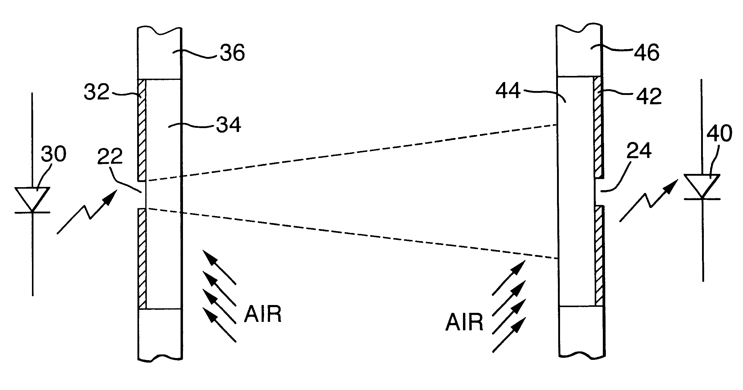
Referring now to FIG. 1, a toolsetting apparatus which is suitable for use on, for example, a machine tool includes a light emitting unit 10 which emits a beam 12 of light, and a light detecting unit 14, where the light beam 12 is detected. Power and signal control cables to the light emitting and detecting units 10,14 are routed via inlet ports 16, and both the units 10,14 are advantageously mounted, via pillars 18, on the base of the machine, either via an intermediate base 20, to which they are both mounted, or directly to the base of the machine upon which they are to be employed.

In operation, the device is used for toolsetting by operating the machine on which the device is mounted to move the tool in a direction transverse to the direction in which the beam 12 is propagating. When a predetermined level of occlusion of the beam has been established, the detecting unit 14 emits a trigger signal which is used by the machine to determine the relative position of its relatively mov...


PUM

PropertyMeasurementUnit
areaaaaaaaaaaa
diameteraaaaaaaaaa
diameteraaaaaaaaaa

Abstract

Described is a device which enables toolsetting on a machine tool. The device includes a light emitting unit (10) and a light detecting unit (14). A light source (30) causes a light beam (12) to propagate from the emitting unit (10) to the detecting unit (14). A light detector (40) detects the presence or absence of the beam. A trigger signal is produced when occlusion occurs and so the position of an object can be determined by reference to the machine's coordinate readings. The beam (12) may be uncollimated and thus provide a device with an easier set-up and a greater resistance to vibration in use. The light detector (40) and / or light source may be protected from contamination by windows (34,44) or a protector having an aperture therein. The light emitting and detecting units each have an aperture for the light beam. The apertures may be oblique conduits (104) for pressurised air flow, thereby keeping the conduits free from contamination, while minimising turbulence in the path of the beam which could cause noise in the resulting signal.

Description

The present invention relates to an apparatus which enables a coordinate positioning machine (such as a machine tool) to determine the position of an object relative to a reference point. It may, for example, be employed on a machine tool for toolsetting operations.DESCRIPTION OF PRIOR ARTA known tool setting device for use on a machine tool includes a light source which generates a fine beam of light which is incident upon a detector. During a toolsetting operation, the machine is operated to move the tool in a direction transverse to the direction of propagation of the light beam until a part of the tool interrupts passage of the light beam. Detection of this interruption results in the generation of a trigger signal in the detecting unit, which is used by the machine to establish the relative position of its moving parts in order to determine dimensions of the tool. Such devices are known, for example, from German Patent Nos. DE 42 385 04 and DE 42 448 69, French Patent No. 2,343...

Claims


Application Information

Patent Timeline
Patent Type & Authority Patents(United States)
IPC IPC(8): B23Q17/24G01B21/02G01B21/04G01B11/02G01B11/00G01V8/12H03K17/94B23Q5/22G01B11/03
CPCB23Q17/24G01B11/005G01B11/028G01B21/047G01V8/12H03K17/94H03K17/941H03K2217/94104H03K2217/94116B23Q17/2485
Inventor STIMPSON, VICTOR GFUGE, JONATHAN PMERRIFIELD, BENJAMIN JMCMURTRY, DAVID R
Owner RENISHAW PLC
Features
  • Generate Ideas
  • Intellectual Property
  • Life Sciences
  • Materials
  • Tech Scout
  • Unparalleled Data Quality
  • Higher Quality Content
  • 60% Fewer Hallucinations
Learn More