
Highly aligned thin film tape head

a magnetic tape and high-alignment technology, applied in the field of thin film magnetic tape recording heads, can solve the problems of expensive skew compensation buffers, complicated logic, and poor tape element alignment in another module, and achieve the effect of improving the alignment of the tape head elemen

Inactive Publication Date: 2002-12-17
STORAGE TECHNOLOGY CORPORATION
View PDF17 Cites 28 Cited by
  • Summary
  • Abstract
  • Description
  • Claims
  • Application Information

AI Technical Summary

Benefits of technology

It is an object of the present invention to provide for improved tape head element alignment.
Another object of the present invention is to provide for decreased skew distances in read-write modules.
Still another object of the present invention is to provide for decreased element alignment errors in multiple module tape heads.
A further object of the present invention is to provide a tape head having closely aligned read and write elements that is economical to produce.

Problems solved by technology

One problem with this technique in multiple module tape heads is that changing the azimuth angle to improve element alignment within one module may worsen element alignment in another module.
Another difficulty is that increasing the azimuth angle introduces a skew distance in the tape direction between write elements and between read elements.
Skew compensation buffers are expensive and require complicated logic.
Alignment problems may be even greater in tape heads constructed with separate read and write modules.
Since it is unlikely that a line can be drawn through the center of all elements accessing a given data track, changing the azimuth angle will not correct for alignment problems in tape heads having separate read and write modules.

Method used


Image

  • Highly aligned thin film tape head
  • Highly aligned thin film tape head
  • Highly aligned thin film tape head

Examples


Embodiment Construction

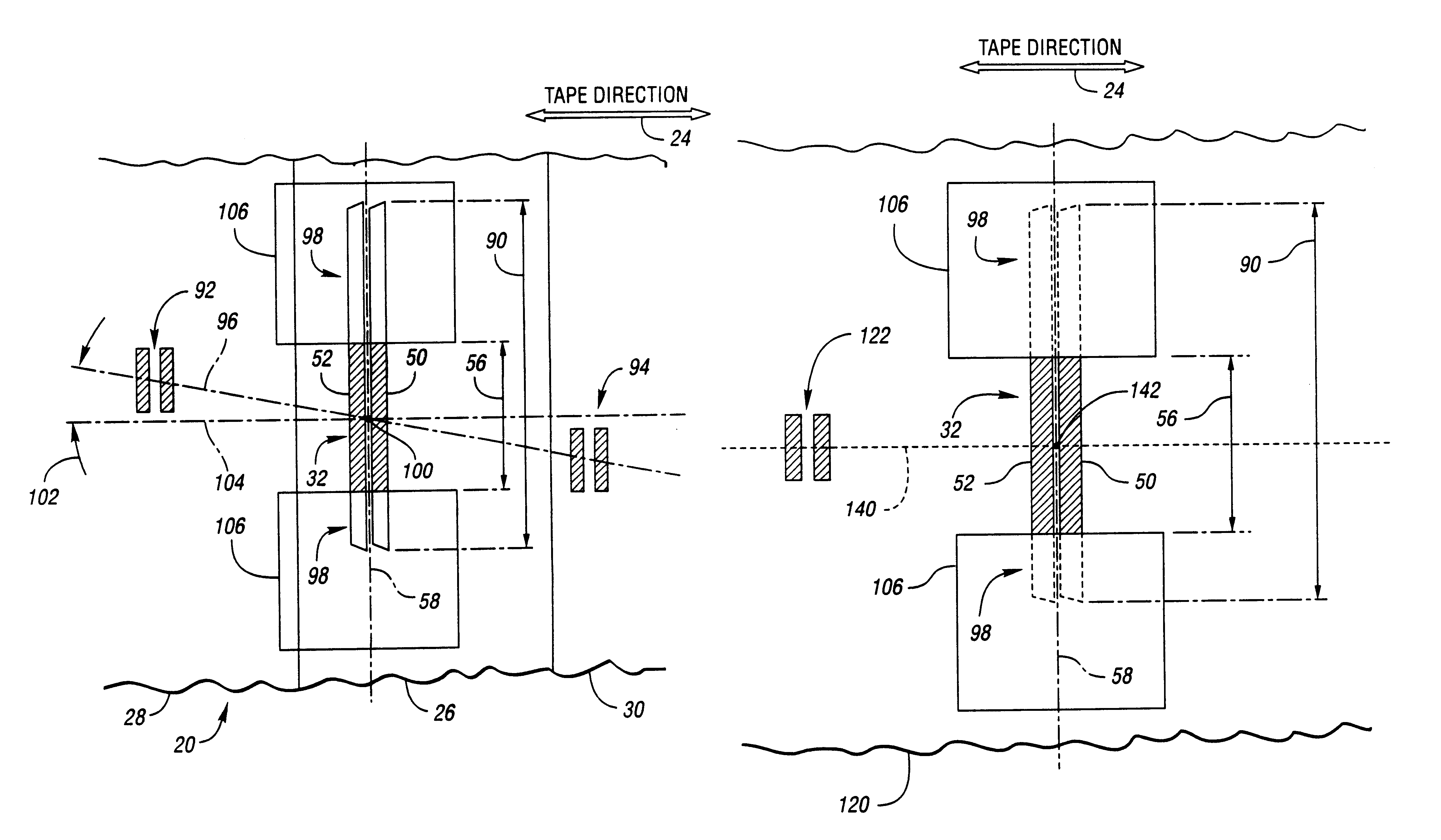
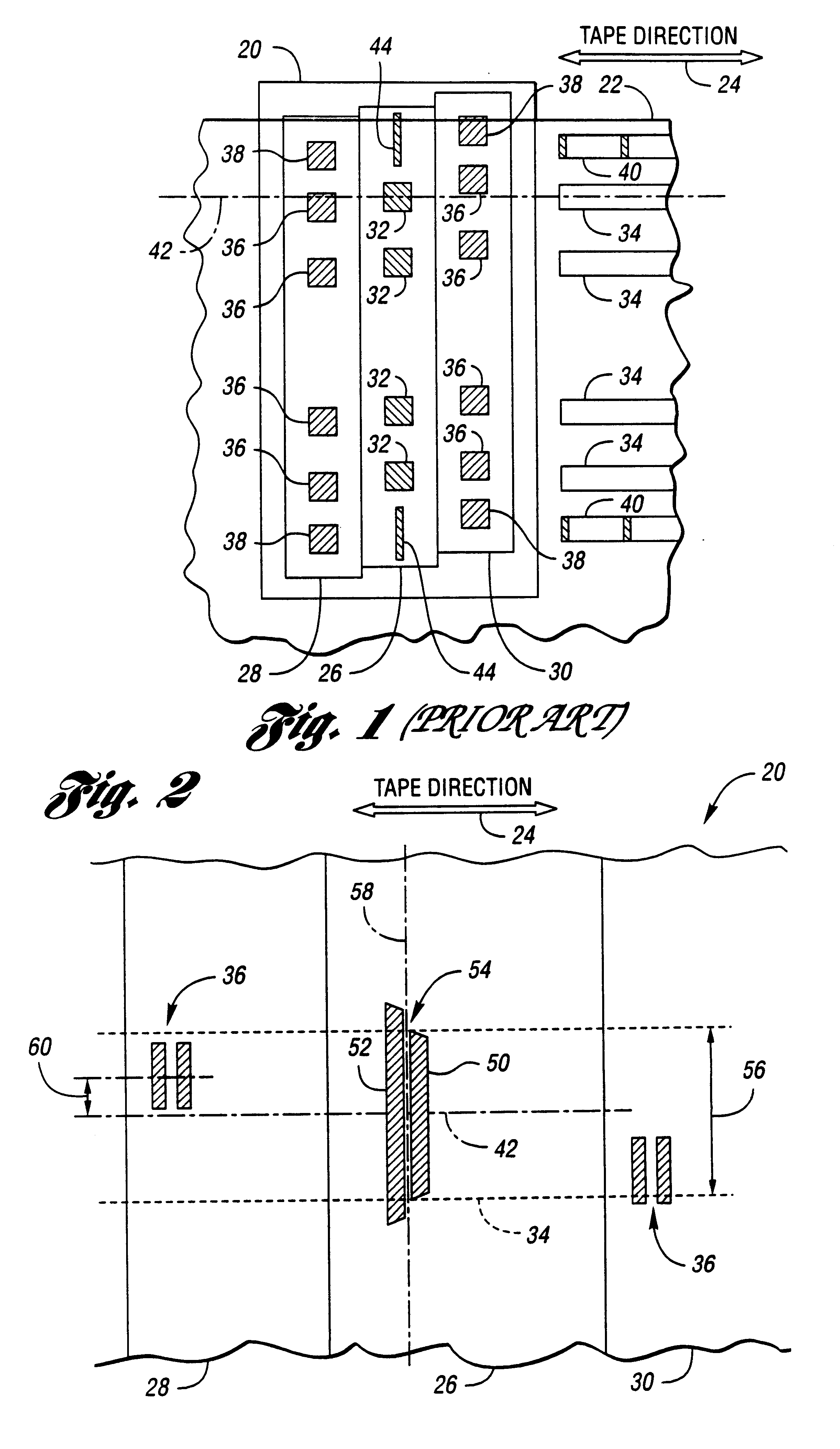
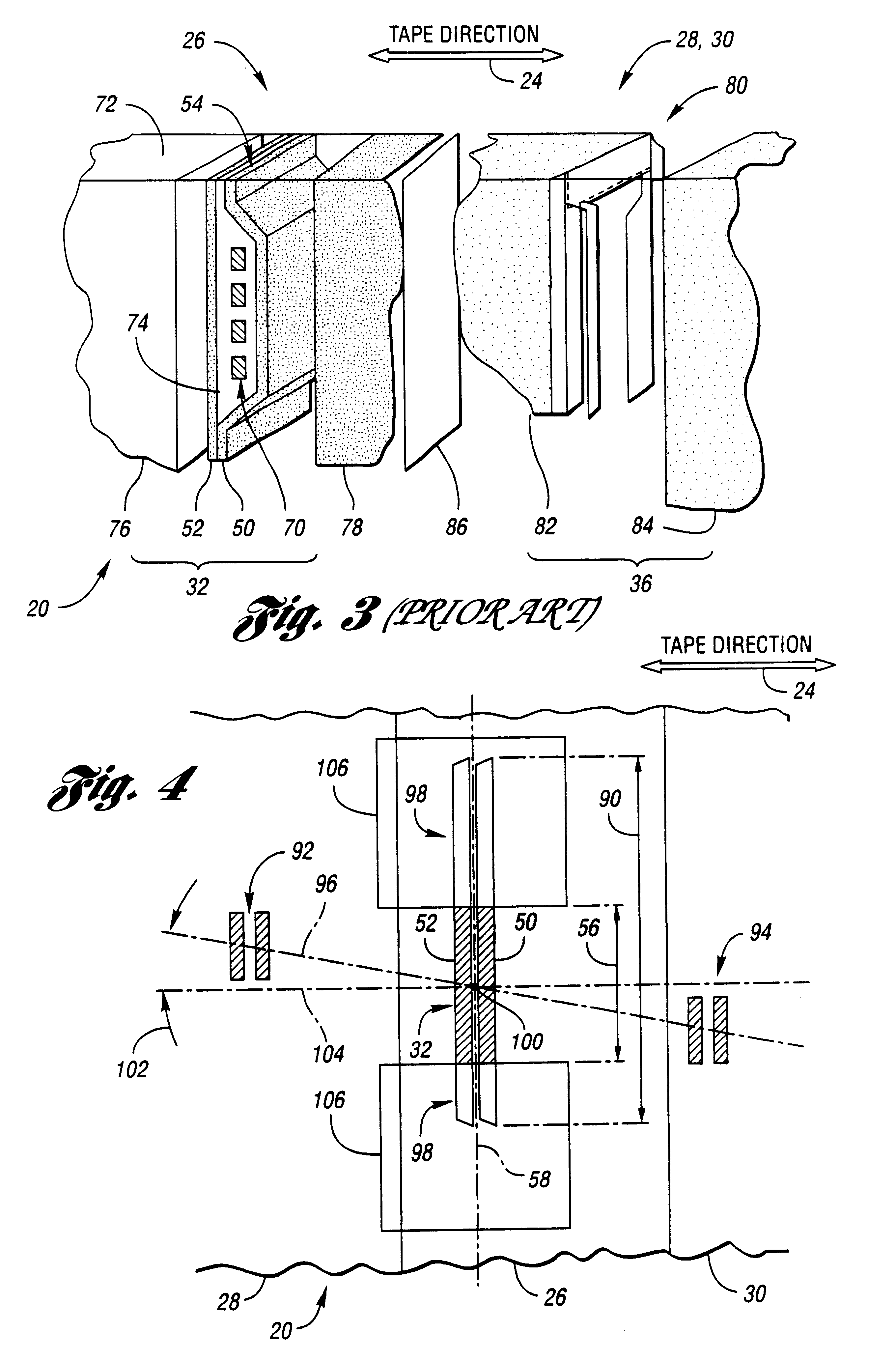
Referring now to FIG. 1, a conceptualized drawing of a prior art read-write-read tape head is shown. Tape head 20 accesses magnetic tape 22 passing by tape head 20 in tape direction 24. Tape head 20 includes write module 26 sandwiched between first read module 28 and second read module 30. Write module 26 includes multiple write elements 32, each operative to write data track 34 on magnetic tape 22. Each read module 28,30 includes one read element 36 corresponding to each write element 32 in write module 26. Each read element 36 can read data from data track 34 on magnetic tape 22.

Typically, at least one read module 28,30 includes servo read elements 38 for reading servo tracks 40 recorded on magnetic tape 22. Patterns recorded on servo track 40 permit tape head 20 to be moved in a direction substantially normal to tape direction 24 to position elements 32,36 over data track 34. For example, data track 34 may be positioned so that data track center 42 is centered over write element ...


PUM

PropertyMeasurementUnit
Lengthaaaaaaaaaa
Widthaaaaaaaaaa
Magnetismaaaaaaaaaa

Abstract

Reducing alignment errors between a read element and corresponding write elements permits narrower data tracks and, hence, greater data density on magnetic tape. A method for manufacturing a thin film tape head having multiple write elements and at least one read element corresponding to each write element is provided. Excess material is trimmed from each write element to align the write element with corresponding read elements. The excess material may be track trimmed using a focused ion beam.

Description

TECHNICAL FIELDThe present invention relates to thin film magnetic tape recording heads for accessing magnetic tape possessing a high degree of alignment between read elements and write elements accessing a particular data track.BACKGROUND ARTReliability, cost-efficiency, and ease of use make magnetic tape the medium of choice for many information storage and retrieval applications. Typically, multiple data tracks are written simultaneously by write elements in a tape head. Similarly, multiple read elements are used to simultaneously sense multiple data tracks. The desire to increase information density held by magnetic tape has resulted in narrower and more closely spaced data tracks. This results in the need for close alignment between head elements which access each data track. This is particularly true for read-after-write operations in which data is read immediately following the write operation to verify the correctness of recorded data.A tape head generally contains multiple ...

Claims


Application Information

Patent Timeline
IPC IPC(8): G11B5/31G11B5/48
CPCG11B5/3103G11B5/3116G11B5/4893G11B5/3163Y10T29/49052Y10T29/49046
Inventor HUNGERFORD, GEOFFREY A.CHESNUTT, ROBERT B.
Owner STORAGE TECHNOLOGY CORPORATION
Learn More