Two-pressure switch

Inactive Publication Date: 2002-12-24
DRNC HLDG INC
View PDF7 Cites 26 Cited by
  • Summary
  • Abstract
  • Description
  • Claims
  • Application Information

AI Technical Summary

Benefits of technology

An object of the invention is thus to mitigate the drawbacks of the prior art by proposing a switch that provides high performance, that is

Problems solved by technology

Not only are additional pieces necessary for keeping the cup out of contact with the substrate, but it is also difficult to master the amount of space that is required between the cup and the substrate in such a situation.
Furthermore, the

Method used


Image

  • Two-pressure switch
  • Two-pressure switch
  • Two-pressure switch

Examples


Embodiment Construction

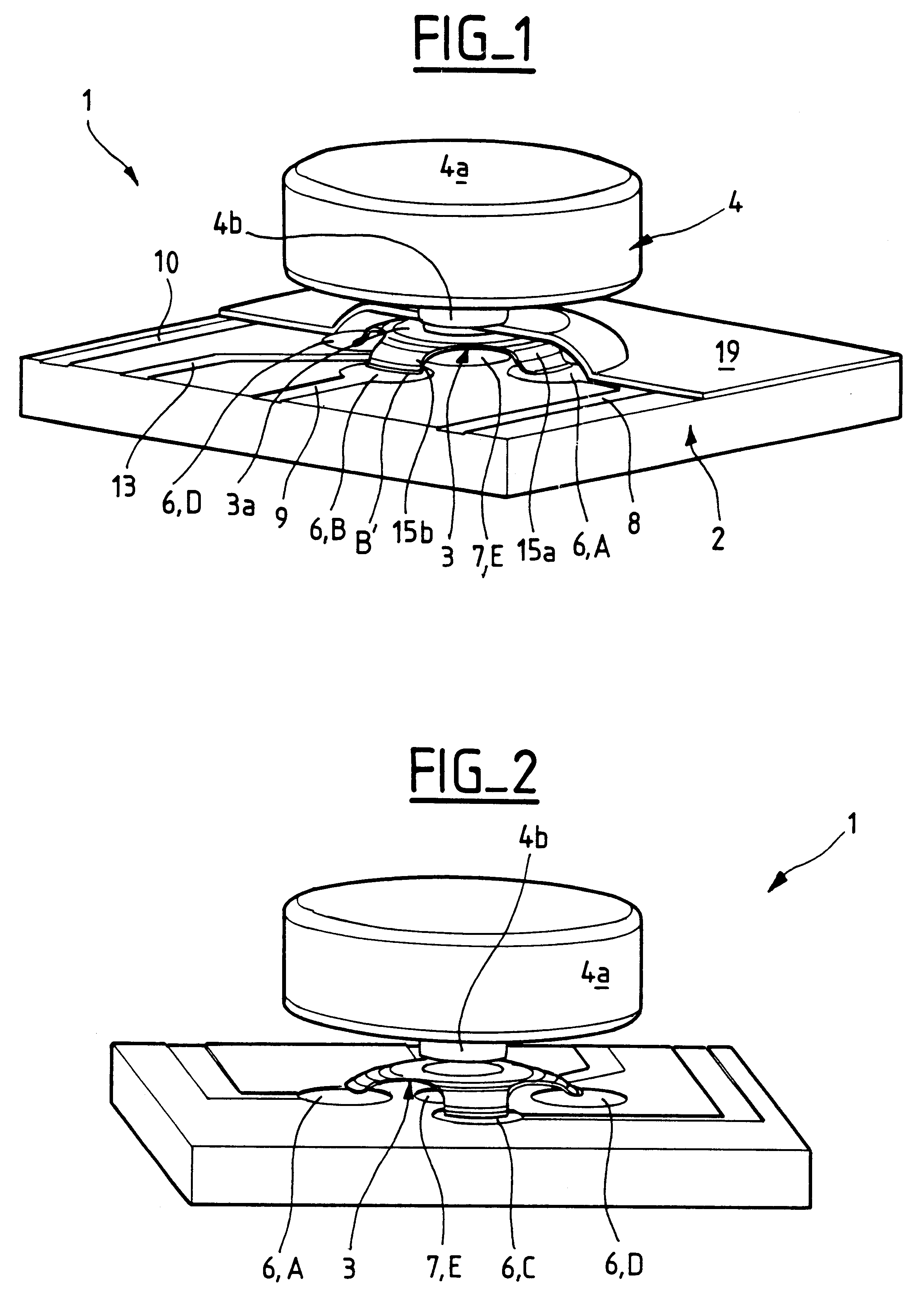
With reference in particular to FIGS. 1 and 2, the switch 1 comprises an insulating substrate 2 having electrical circuits and tracks, and surmounted by a spring 3 suitable for making contact with the electrical circuits.

To make such contact, the spring 3 is moved and deformed under the effect of pressure exerted on the outside face 3a thereof by a key 4.

Each of the elements forming the switch 1 of the invention is described below in detail.

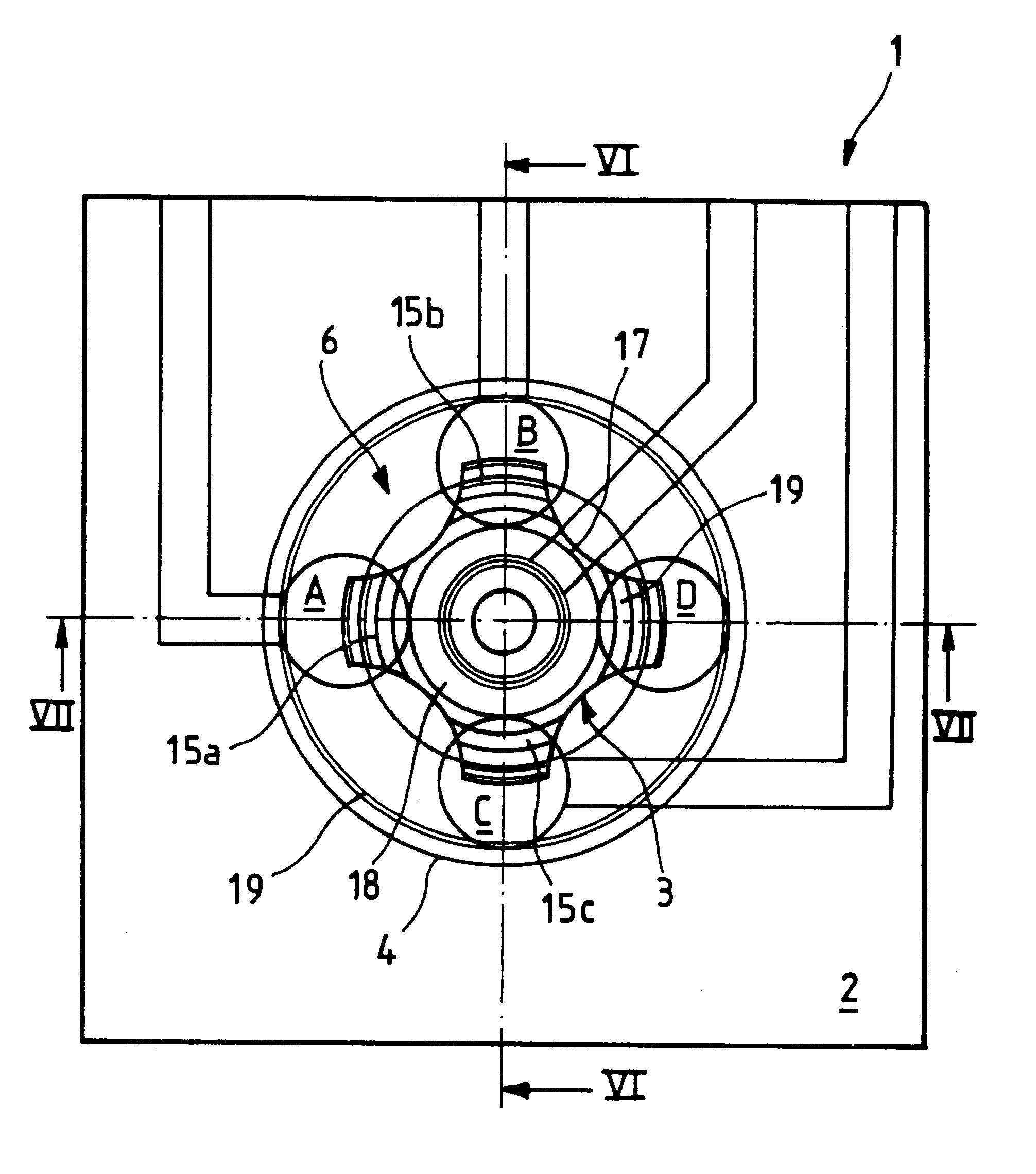
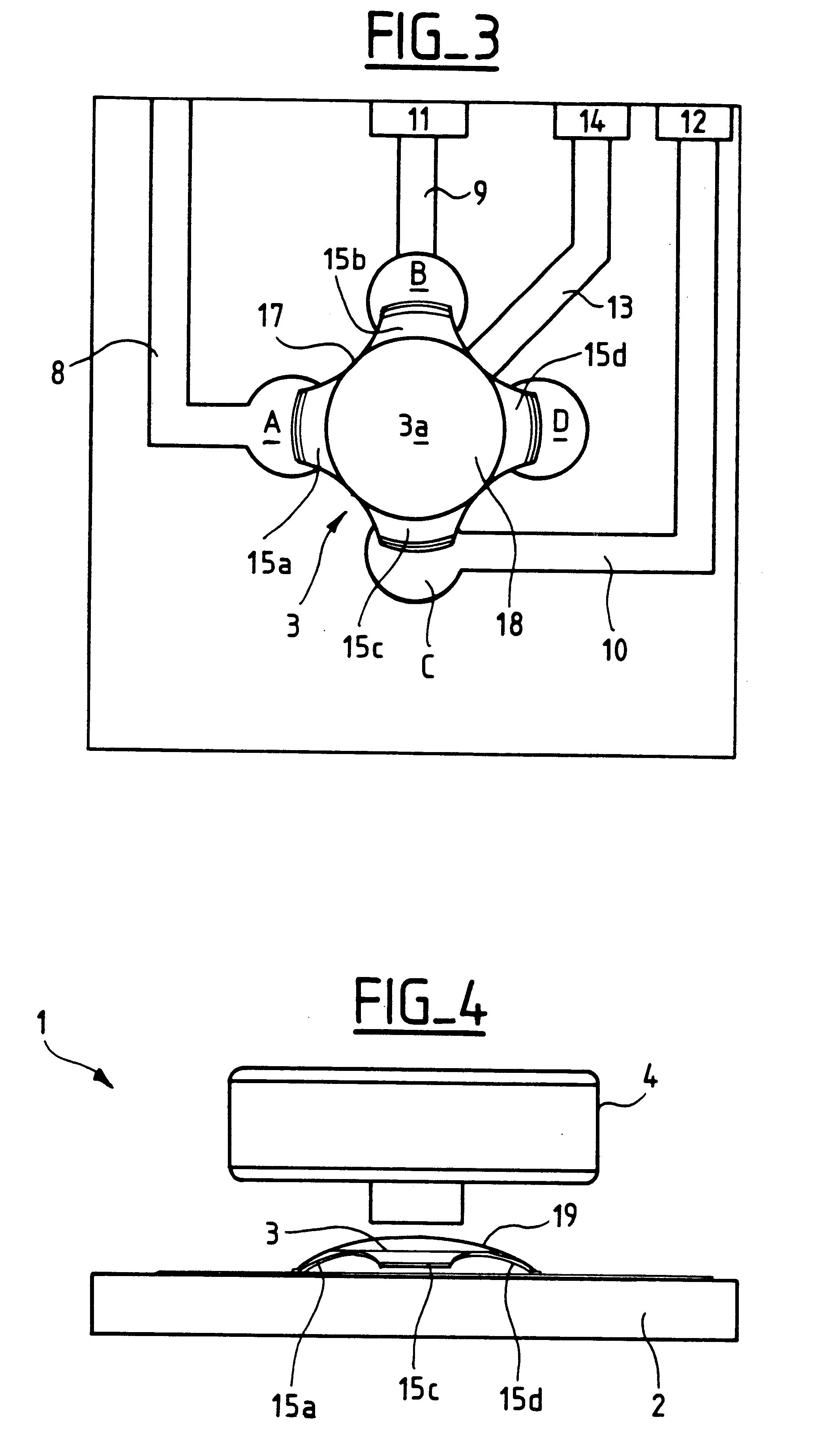
As shown in FIGS. 1 to 3, the insulating substrate 2 is formed by a plate having first and second conductive zones 6 and 7 each lying within a respective substantially circular annulus. The first conductive zone 6 lies outside the second conducive zone 7.

The first conductive zone 6 comprises four conductive portions A, B, C, and D which are electrically insulated from one another.

Each of these portions A, B, C, and D is generally in the shape of a disk. Naturally, other shapes could be envisaged.

The portions A to D are distributed circumferential...


PUM


Abstract

A press switch comprises an insulating substrate with two conductive zones suitable for triggering first and second functions, respectively. The first zone has at least two portions that are electrically insulated from each other. A spring has two contact zones, one of which includes at least two regions that are electrically interconnected and suitable for making contact with respective portions. In a rest position, the spring makes contact with at least part of the first conductive zone, and no function is performed. In a first actuated position, a first amount of pressure applied to the spring causes it to make full contact with the first conductive zone, thereby causing the first function to be performed. In a second actuated position, a second amount of pressure causes contact to be made by each contact zone with the respective conductive zone, and the said function is performed.

Description

The invention relates to a press switch for controlling at least two functions in response to respective pressures exerted on the switch.Such a switch is used for various types of electrical equipment, such as cameras, video cameras, or telephones, for example. The purpose of such a switch is specifically to minimize the number of keys in such equipment, or to make it more ergonomic.With this type of switch, a first press at lower pressure actuates a first function, for example a preparatory mode such as preselection. Thereafter, a second press at higher pressure serves to actuate a second function, for example an operating mode such as validating the preselection.Document U.S. Pat. No. 5,313,027 discloses a switch of the above type comprising an insulating substrate having an outer annular contact zone and an inner annular contact zone. A deformable conductive cup disposed in register with said zones is adapted to be in contact firstly with the outer zone on being subjected to a fi...

Claims


Application Information

Patent Timeline
IPC IPC(8): H01H13/50H01H13/64H01H13/48H01H25/04H01H13/66
CPCH01H13/64H01H13/48H01H2225/018
Inventor VILLAIN, JEAN-CHRISTOPHE
Owner DRNC HLDG INC
Why Eureka
Try Eureka