Bearing apparatus

a bearing and ring technology, applied in the field of bearing ring devices, can solve the problems of shortening the service life of the bearing ring apparatus, and also the service life of the motor, and reducing so as to reduce the power consumption, prolong the service life of the bearing ring apparatus, and effectively use

Inactive Publication Date: 2002-12-24
SANKYO SEIKI MFG CO LTD
View PDF8 Cites 20 Cited by
  • Summary
  • Abstract
  • Description
  • Claims
  • Application Information

AI Technical Summary

Benefits of technology

It is an object of the present invention to provide a bearing apparatus having an active magnetic bearing that requires electrical power that is used only to control vibration components. As a result, the bearing apparatus in accordance with the present invention reduces the power consumption, securely prevents contacts between a rotator body and a non-rotation body and substantially extends the service life of the bearing apparatus.
It is another object of the present invention to provide a bearing apparatus that may include a thrust dynamic pressure bearing and an active magnetic bearing provided in combination such that characteristics of the respective bearings are effectively used. For example, the static rigidity is born by the active magnetic bearing and the dynamic rigidity is born by the dynamic pressure bearing. As a result, the bearing apparatus has a higher accuracy and a longer service life and can reduce the load torque at the time of starting its rotation, compared to a bearing apparatus that uses only a thrust dynamic pressure bearing or an active magnetic bearing.
It is still another object of the present invention to provide a bearing apparatus that may include a thrust dynamic pressure bearing and an active magnetic bearing used in combination. In one aspect of the present embodiment, the load applied to the dynamic pressure bearing is reduced compared to a bearing apparatus that uses only a dynamic pressure bearing, the distance of a fine gap that forms the dynamic pressure bearing can be made relatively large, the need to strictly manage the working precision and assembly accuracy for parts of the dynamic pressure bearing can be eliminated, and the manufacturing cost is lowered.

Problems solved by technology

Also, since a thrust dynamic bearing supports the weight in the direction of gravity, the rotator body may often contact the non-rotation body when the rotation is stopped, which results in shortening the service life of the bearing apparatus, and also the service life of the motor.
However, the thrust bearing formed from a magnetic bearing has the following problems.
As a result, the motor suffers a large amount of losses.
Since the magnetic bearing has a lower dynamic rigidity compared to the dynamic pressure bearing, it is rather vulnerable to high frequency vibrations compared to the dynamic pressure bearing.

Method used


Image

  • Bearing apparatus
  • Bearing apparatus
  • Bearing apparatus

Examples


Embodiment Construction

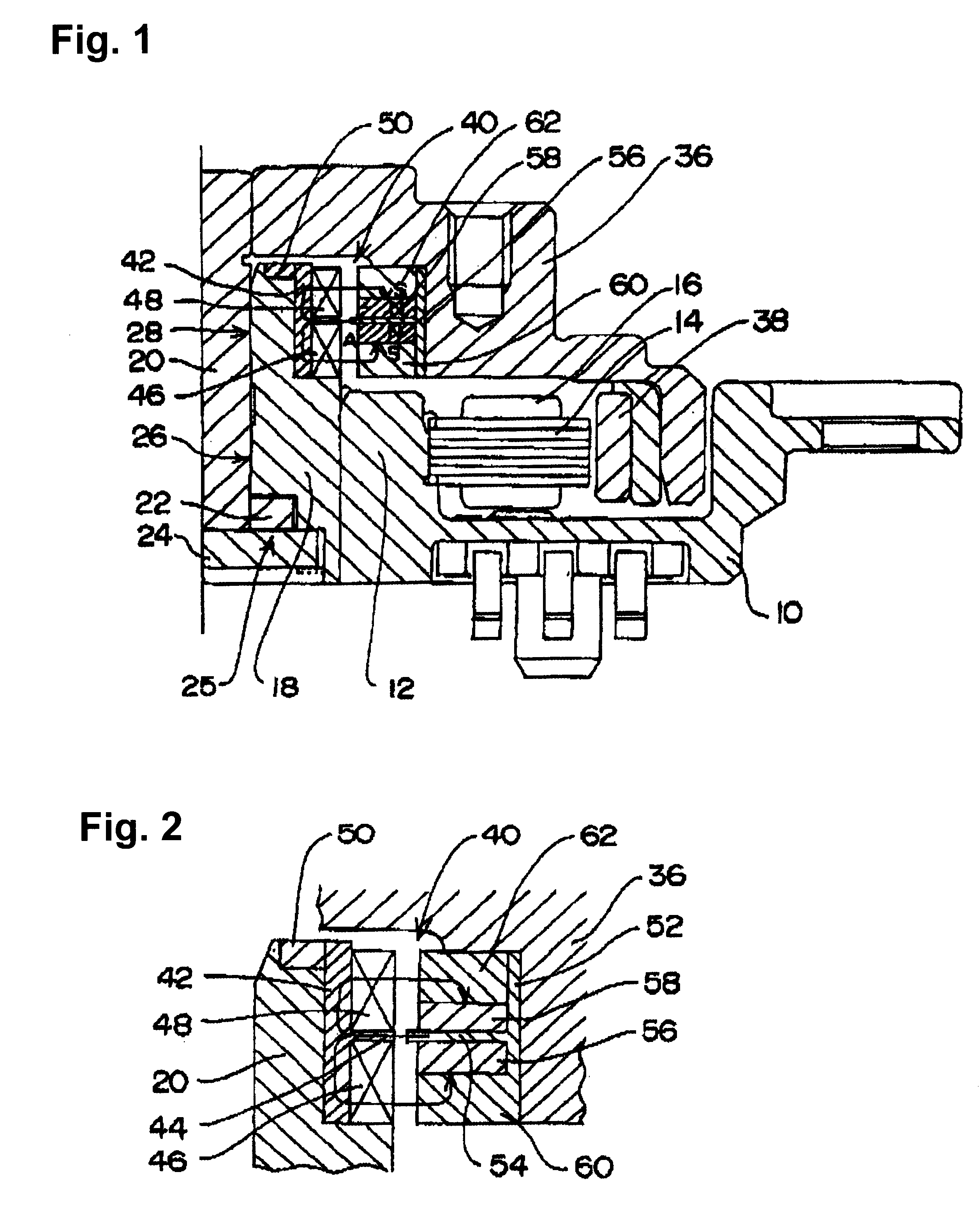
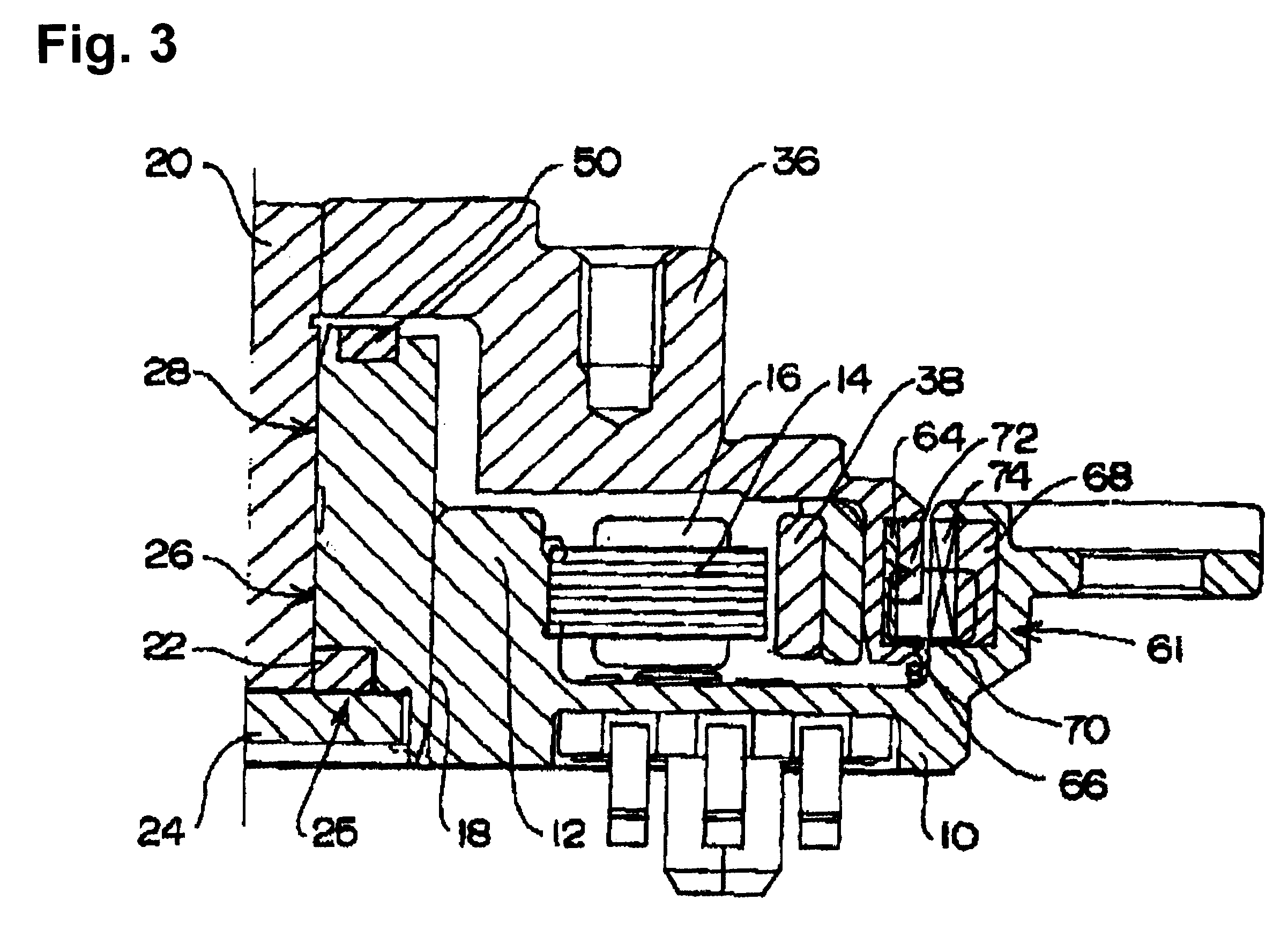
A bearing apparatus in accordance with an embodiment of the present invention is described below with reference to the accompanying drawings.

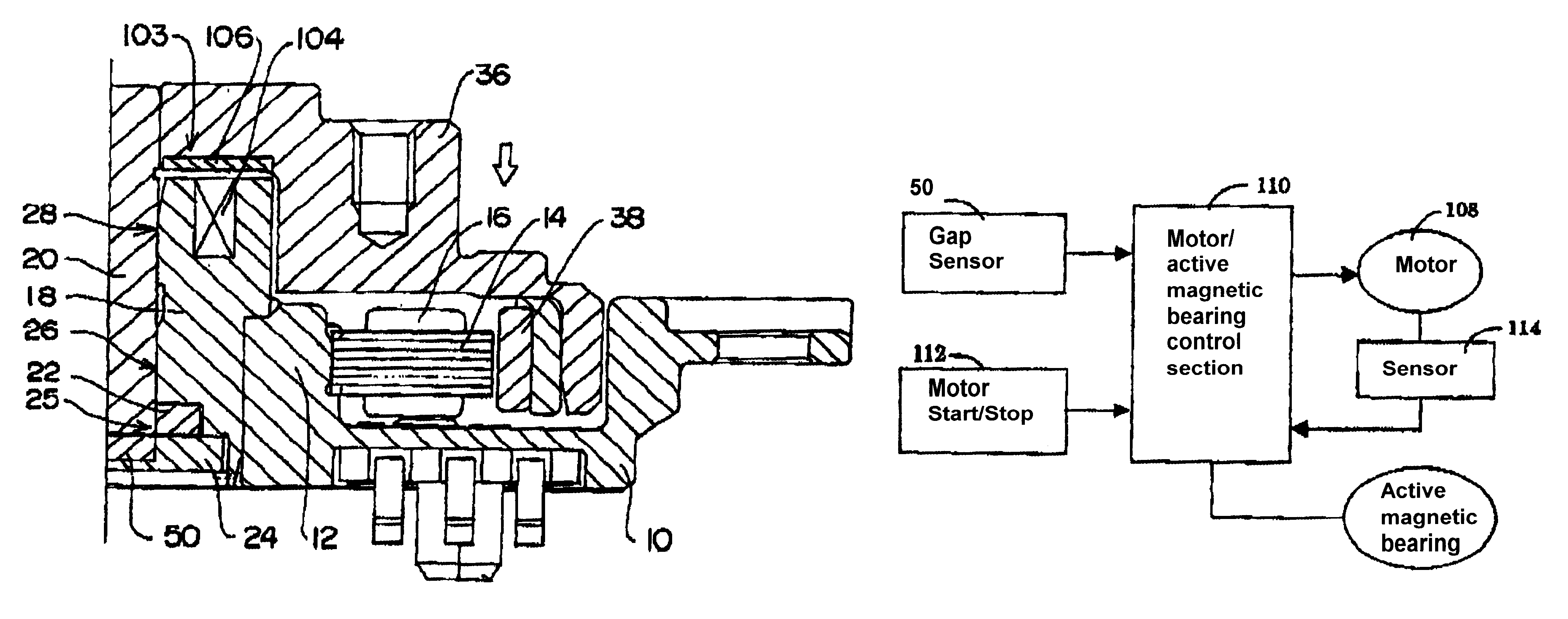
Referring to FIG. 1, a frame 10 of a motor includes a cylindrical holder section 12 formed in one piece with the frame 10 in a central section of the frame 10. A stator core 14 is affixed to the holder section 12 with an internal surface of the stator core 14 being in a pressure contact with an external peripheral surface of the holder section 12. The stator core 14 is a stacked layered core, and has a plurality of radially extending salient poles. A driving coil 16 is wound around each of the salient poles.

A cylindrical bearing member 18 is inserted in the holder section 12 and affixed to an internal peripheral side of the holder section 12. A rotor shaft 20 as a rotator body is inserted in a central bore of the bearing member 18, and the rotor shaft 20 is relatively rotatably supported by the bearing member 18. A thrust plate 22 is coupled an...


PUM

PropertyMeasurementUnit
static rigidityaaaaaaaaaa
dynamic rigidityaaaaaaaaaa
dynamic pressureaaaaaaaaaa

Abstract

A bearing apparatus includes a rotator body, a non-rotation body rotatably supporting the rotator body, and a lubrication fluid provided between the rotator body and the non-rotation body in which the rotator body is supported in a thrust direction by a thrust dynamic pressure bearing formed between the rotator body and the non-rotation body. The bearing apparatus includes an active magnetic bearing formed by a driving coil disposed on one of the rotator body and the non-rotation body and a magnet disposed on the other thereof, and a gap sensor that detects an axial direction gap between the rotator body and the non-rotation body. The thrust dynamic pressure bearing and the active magnetic bearing are combined such that the static rigidity of the bearing apparatus is born by the active magnetic bearing and the dynamic rigidity is born by the dynamic pressure bearing.

Description

1. Field of the InventionThe present invention relates to a bearing apparatus having a rotator body and a non-rotation body in which the rotator body is supported in a thrust direction by a thrust dynamic pressure generated between thrust bearing surfaces of the rotator body and the non-rotation body, which is applicable as, for example, a bearing apparatus of a hard disc drive motor, and a variety of optical disc drive motors.2. Description of Related ArtA variety of strict demands in higher accuracy at higher speeds, longer service life, and lower noise are imposed on small size spindle motors that are used for hard disc drive apparatuses and various optical disc drives. To meet the demands, it is effective to make bearing apparatuses with dynamic pressure bearings. In this connection, a bearing apparatus in which its radial bearing and thrust bearing are both formed by dynamic pressure bearings has been developed.A typical dynamic pressure bearing uses a lubrication fluid filled ...

Claims


Application Information

Patent Timeline
Patent Type & Authority Patents(United States)
IPC IPC(8): H02K7/09H02K7/08F16C17/10F16C32/00F16C32/04G11B19/20
CPCH02K7/09F16C39/06F16C17/107H02K7/085F16C2370/12
Inventor KANEBAKO, HIDEKI
Owner SANKYO SEIKI MFG CO LTD
Why Eureka
Try Eureka