
Caged roller assembly and reduction gear unit using the same

a technology of cage rollers and gear units, which is applied in the direction of roller bearings, mechanical equipment, roller bearings, etc., can solve the problems of difficult to reduce the circumferential space between cage rollers, rollers tend to skew, and full-type roller assemblies have a handling problem

Inactive Publication Date: 2003-02-04
NTN CORP
View PDF10 Cites 30 Cited by
  • Summary
  • Abstract
  • Description
  • Claims
  • Application Information

AI Technical Summary

Problems solved by technology

While a full type roller assembly without a roller retainer is currently available as a bearing capable of exhibiting a maximum load bearing capacity within a limited space, it has been recognized that the full type roller assembly has a handling problem, specifically difficulty in assemblage and overhauling, and often involves a potential functional problem in that some of the rollers tend to skew during the use of the bearing.
With this structure, since the pillar extending radially is disposed between the neighboring rollers, it is difficult to decrease a circumferential space between such rollers to thereby increase the number of rollers employed therein.
In the well known prior art caged roller assembly discussed above, since the rollers are retained in position by the radially outer and inner roller stoppers formed on respective pillars of the roller retainer, it has often been observed that the oil film on the rolling surfaces of the rollers tends to be depleted in sliding contact with the roller stoppers.
Also, in the planetary reduction gear unit of this kind, support of the planetary gears requires a relatively large load and a support sections tends to be a limited space.

Method used


Image

  • Caged roller assembly and reduction gear unit using the same
  • Caged roller assembly and reduction gear unit using the same
  • Caged roller assembly and reduction gear unit using the same

Examples


Embodiment Construction

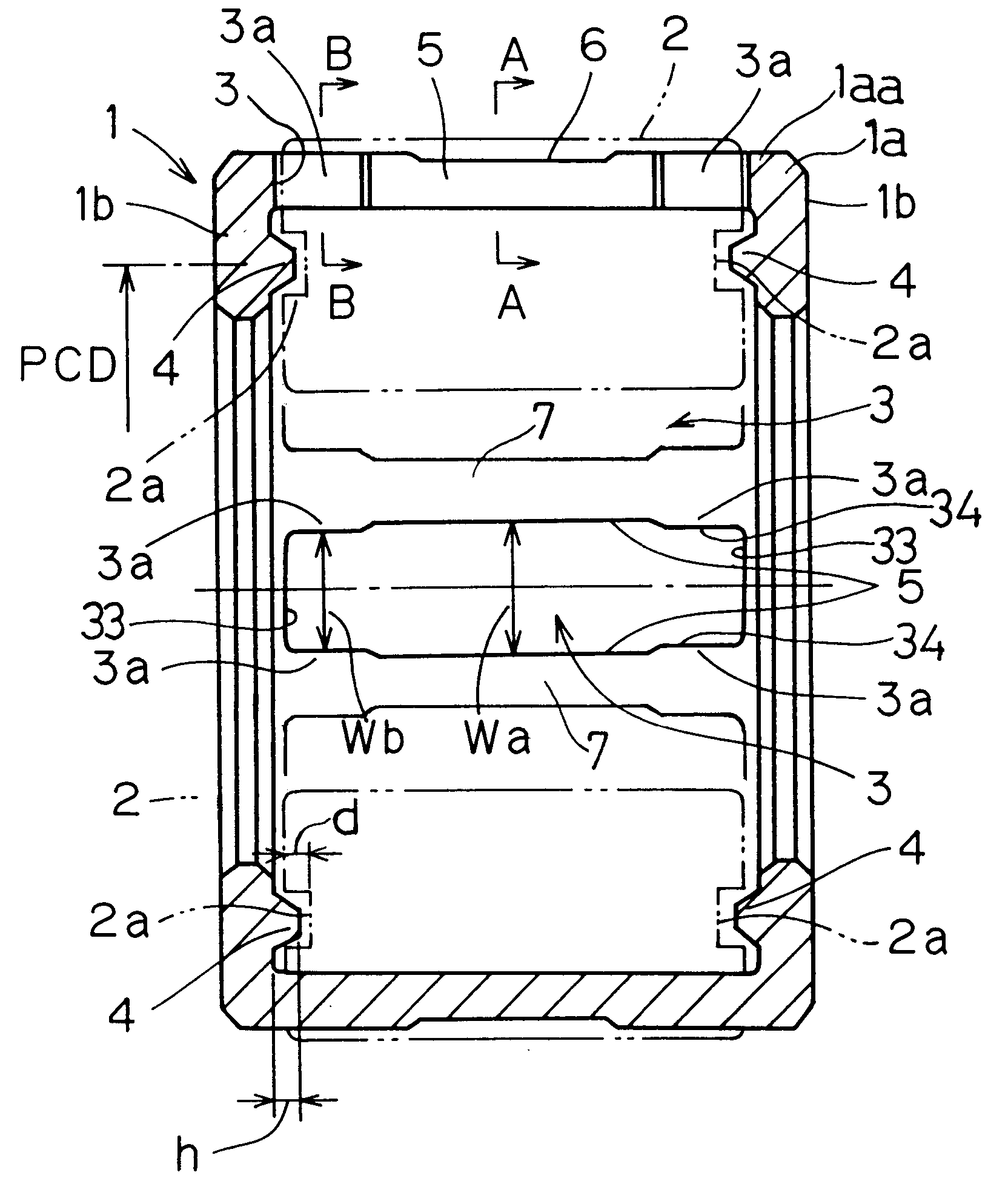
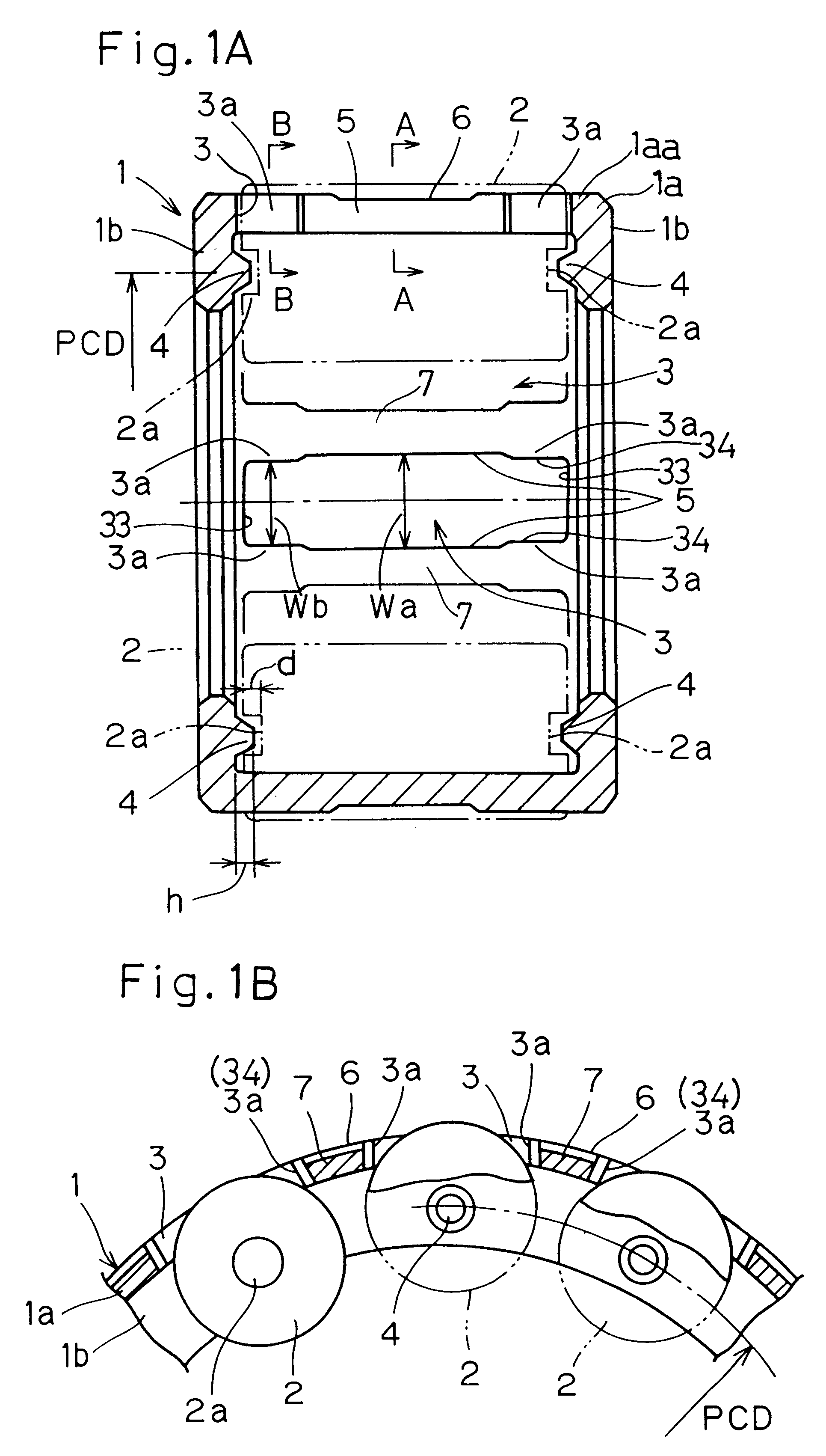
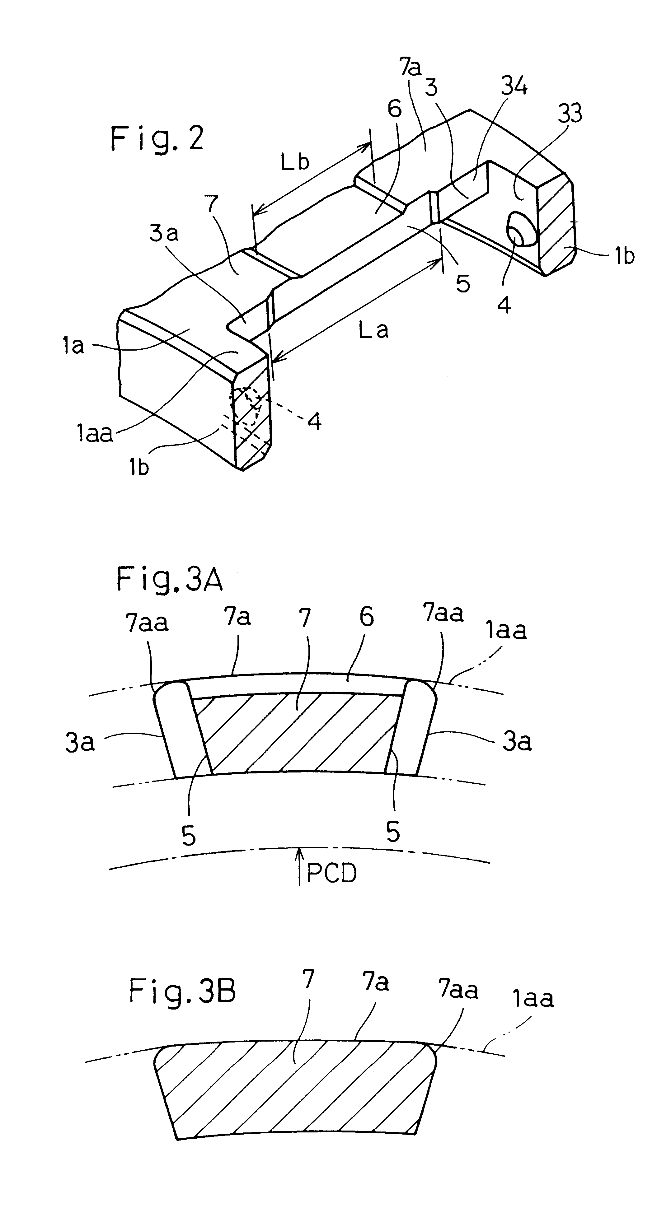
Referring first to FIGS. 1A to 3B pertaining to a first preferred embodiment of the present invention, a caged roller assembly shown therein includes a cylindrical roller retainer or cage 1 shown in FIG. 1A and a plurality of needle rollers 2 retained rollingly by the roller retainer 1 with their axes of rotation depicting the pitch circle PCD. The roller retainer 1 is made up of a radially circumferential ring body 1a positioned radially outwardly of the pitch circle PCD and having ends axially opposite to each other, and an annular collar or flank 1b formed preferably integrally with the radially circumferential ring body 1a so as to extend a predetermined distance radially inwardly from each of the opposite ends of the radially circumferential ring body 1a.

A plurality of generally rectangular pockets 3 are defined in the circumferential ring body 1a and are spaced an equal distance from each other in a direction circumferentially of the circumferential ring body 1a, with a longit...


PUM

PropertyMeasurementUnit
diameteraaaaaaaaaa
depthaaaaaaaaaa
distanceaaaaaaaaaa

Abstract

To provide a caged roller assembly having a large load bearing capacity within a limited space, substantially free from a problem associated with separation of rollers from a roller retainer in either direction radially outwardly or inwardly of the roller retainer, and excellent in assemblability while a skewing of the roller is prevented, the caged roller assembly includes a roller retainer (1) and a plurality of rollers (2). The roller retainer (1) includes a circumferential ring body (1a) of a diameter greater than the pitch circle PCD depicted by longitudinal axes of the rollers (2), and a pair of annular collars or flanks (1b) lying perpendicular to the circumferential ring body (1a). A bearing boss (4) for each roller (2) is formed in each of the annular flank (1b) on one hand, and a bearing recess (2a) is defined in each of opposite end faces of each roller (2) for operatively receiving the respective bearing bosses (4) to thereby rotatably support the associated roller (2) in a non-detachable fashion.

Description

1. Field of the InventionThe present invention relates to a caged roller assembly having a high load bearing capacity within a limited space and a planetary reduction gear unit using such caged roller assembly.2. Description of the Prior ArtIt is known that caged roller assemblies or caged roller assemblies are used in planetary reduction gear unit employed in various applications including, for example, construction machines. This type of caged roller assemblies has long been and is currently desired to have an increased load bearing capacity. While a full type roller assembly without a roller retainer is currently available as a bearing capable of exhibiting a maximum load bearing capacity within a limited space, it has been recognized that the full type roller assembly has a handling problem, specifically difficulty in assemblage and overhauling, and often involves a potential functional problem in that some of the rollers tend to skew during the use of the bearing. To alleviate ...

Claims


Application Information

Patent Timeline
Patent Type & Authority Patents(United States)
IPC IPC(8): F16C33/46F16C9/02F16H1/32F16C19/26
CPCF16C33/4682F16C33/4635F16C19/26F16C2361/61F16C2208/60
Inventor TAKAHASHI, YASUAKIABE, KATSUFUMI
Owner NTN CORP
Learn More