Method and apparatus for adaptive cancellation of responses in cabling

a technology of adaptive cancellation and response, applied in the direction of resistance/reactance/impedence, line-transmission details, instruments, etc., can solve the problems of user patch cord unpopularity, data transmission capability questionable, definition may be problematic,

Inactive Publication Date: 2003-02-18
MICROTEST
View PDF14 Cites 80 Cited by
  • Summary
  • Abstract
  • Description
  • Claims
  • Application Information

AI Technical Summary

Problems solved by technology

If the NEXT value exceeds the limit, then it is considered to have failed, and its data transmission capability is questionable.
One field test problem arises from the definition of the components of the cabling that are to be included in the channel field test measurements.
This definition may be problematic as measurements must necessarily be made through these connections.
It is impractical (and unpopular) to cut off a connector from the user's patch cord to make the test as it is often done in laboratory environments.
These connections can have a considerable affect on the measurement and mask the true performance of the channel under test.
Often the contributions of these connections will cause an otherwise compliant link to fail.
Currently this channel measurement problem is not addressed adequately by any field test equipment.
This may result in an inaccurate measurement of channel 100.
Level I Accuracy instruments are generally not considered adequate for testing of new, high performance cabling systems.
While this method may appear to be a solution, in fact, there can be significant differences between the amount of crosstalk, return loss, and the like contributed by the specific jack and plug comprising the connection.
The variability often results in tradeoffs made by each manufacturer and physical issues associated with terminating a plug onto a cable.
Therefore, it may not be possible to have a priori knowledge of a suitable connection contribution that must be cancelled.
That is, subtraction of "nominal" crosstalk from measured data can increase the amount of indicated crosstalk, return loss and the like.
Thus, it is unlikely that test equipment utilizing this method of correction, known as fixed vector cancellation, could qualify for better than Level I performance.
However, this method suffers from additional shortcomings.
For example, one problem with time gating results from the fact that there is limited bandwidth available in the frequency domain, and thus limited time resolution to perform the time gating.
A second limitation of the time gating method primarily affects the return loss measurement.
Time gating for return loss measurements can lead to significant errors due to ignoring the initial cable impedance mismatch as well ignoring reflections in the first few feet of the cable.
Time gating results in missing an important portion of the crosstalk or return loss in the user's patch cord.
Current field testers that implement some form of time gating typically ignore up to the first 3 to 4 feet of the user patch cable due to bandwidth and sampling considerations.
This extremely wide bandwidth requirement is beyond the current state of field test equipment.
Current field test instruments use time domain techniques to identify and time-gate out sources of NEXT and return loss in, but they do not use this information to estimate the magnitude, phase and position of these sources so they can be cancelled.

Method used


Image

  • Method and apparatus for adaptive cancellation of responses in cabling
  • Method and apparatus for adaptive cancellation of responses in cabling
  • Method and apparatus for adaptive cancellation of responses in cabling

Examples


Embodiment Construction

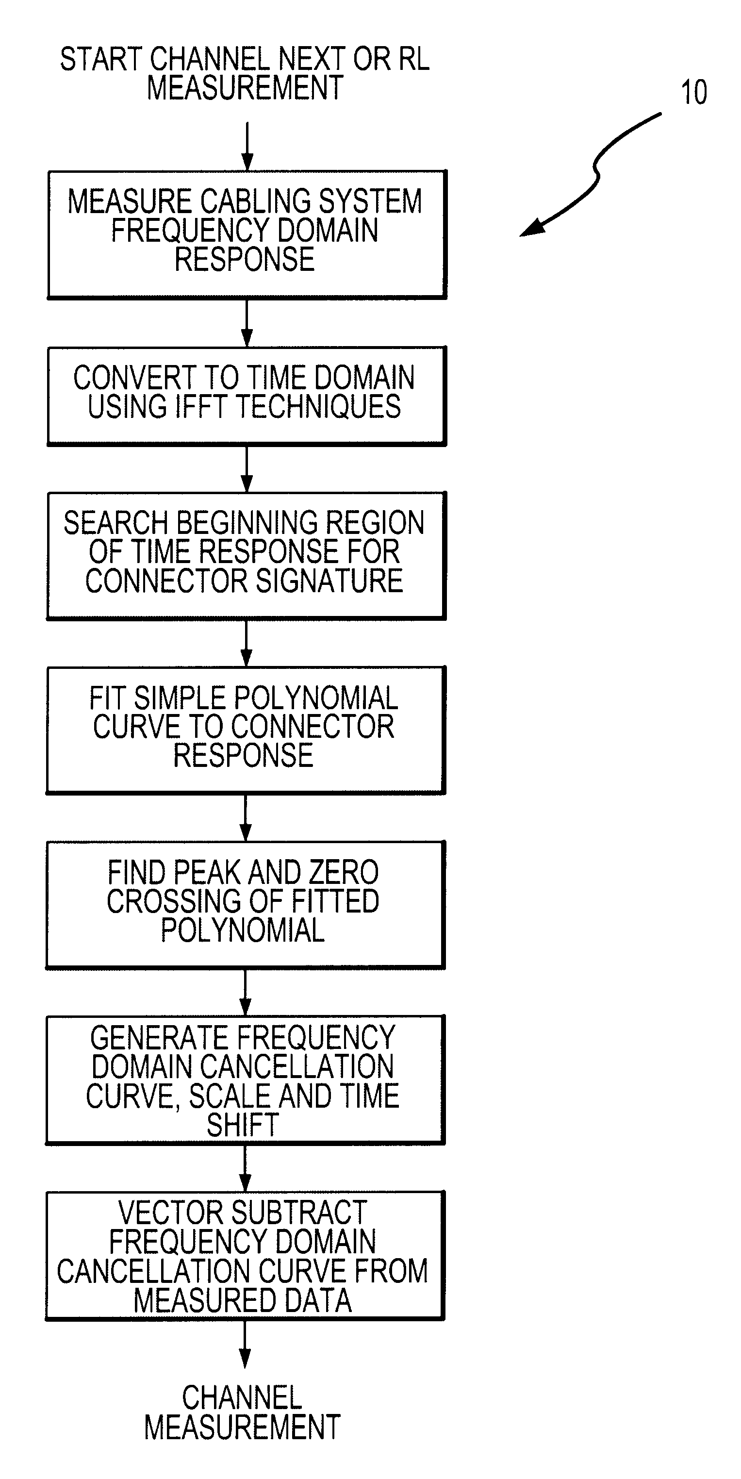
The following descriptions are of exemplary embodiments only, and are not intended to limit the scope, applicability, or configuration of the invention in any way. Rather, the following description provides convenient illustrations for implementing a preferred embodiment of the invention. Various changes may be made in the function and arrangement of the elements described in the preferred embodiments without departing from the spirit and scope of the invention as set forth in the appended claims. For example, while the following description is directed largely to cancellation of connector response, likewise, it should be appreciated that the exemplary methods described herein also apply to cancellation of responses in other portions of cabling links.

The present invention relates generally to a method to estimate the idealized time-domain performance of a test equipment interface and to apply the estimate to frequency domain data measured through the interface with the purpose of re...


PUM


Abstract

An Adaptive Vector Cancellation method which uses time domain data for an instrument connection to estimate magnitude, phase, and time position of a signal response such as NEXT or Return Loss associated with the connection. Based on the estimate of the amplitude and time of the connection response, a suitable full-bandwidth frequency response that corresponds to a point source of NEXT or Return Loss is determined. This calculated connector response is then scaled to an appropriate magnitude, phase and time shifted to the estimated position of the actual connection. The scaled / shifted response is then vectorially combined with the measured sweep data to suitably cancel the connection contribution to NEXT and / or Return Loss. Thus, the amount of NEXT or return loss existing in the user's patch cord is preserved, while the NEXT or return loss due to the instrument connection is suitably suppressed. Correction is done in the frequency domain, over the full bandwidth of the measured data.

Description

BACKGROUND OF INVENTION1. Technical FieldThis invention relates generally to the use of signal processing techniques for determining the transmission performance data of cabling systems, and more particularly, to techniques for canceling undesired signals in cabling systems.2. Background of the InventionThe transmission performance characteristics of modern high speed data communication twisted pair cabling systems are defined by various international and industry working bodies (standards organizations) to assure standard data communication protocols can successfully be transmitted through the transmission media. These data communication cabling systems (known as channels) typically consist of connectors (modular 8 plugs and jacks) and one or more forms of twisted pair cabling. The requirements for important RF transmission performance parameters such as Near End Crosstalk (NEXT), Return Loss, Insertion Loss, and Equal Level Far End Crosstalk (ELFEXT) are typically specified as a f...

Claims


Application Information

Patent Timeline
Patent Type & Authority Patents(United States)
IPC IPC(8): G01R31/11G01R31/08
CPCG01R31/11G01R31/083
Inventor TONTI, JAMES G.PATTERSON, JAMES A.SCIACERO, JAMES R.
Owner MICROTEST
Why Eureka
Try Eureka