System, method and program for determining the magnetic center shift within a disk drive system

a disk drive system and magnetic center technology, applied in the field of system, method and program for determining the magnetic center shift within the disk drive system, can solve the problems of mcs affecting the ability of the read sensor to measure any signal accurately, the deviation of the read sensor from the center of the track being read, and the inability of the mr head to properly read data from the storage surfa

Inactive Publication Date: 2003-02-18
HITACHI GLOBAL STORAGE TECH NETHERLANDS BV
View PDF13 Cites 12 Cited by
  • Summary
  • Abstract
  • Description
  • Claims
  • Application Information

AI Technical Summary

Problems solved by technology

Errors in the ability of an MR head to properly read data from the storage surface can be caused, in part, by track misregistration due to head positioning irregularities on a rotating disk, track interference, and head (magnetic) domain noises.
Notwithstanding attempts to bias the head to make the signal more symmetric, the MCS noise caused by the magnetic fields of the write head still cause the read sensor to deviate from the center of the track being read.
Especially problematic is that MCS affects the ability of the read sensor to measure any signal accurately.
Thus, MCS will produce feed forward errors when the read TMR is used to determine a corrective error signal in the closed loop servo system used in disk drives because the signal used in determining the read TMR would include asymmetries.
The greater the read head is off-center, the greater the likelihood of errors and noise in reading and writing data from the storage surface of the disk.
This increase in noise reduces the signal to noise ratio and the overall quality of data operations.
One problem with current techniques for measuring MCS, includ

Method used


Image

  • System, method and program for determining the magnetic center shift within a disk drive system
  • System, method and program for determining the magnetic center shift within a disk drive system
  • System, method and program for determining the magnetic center shift within a disk drive system

Examples


Embodiment Construction

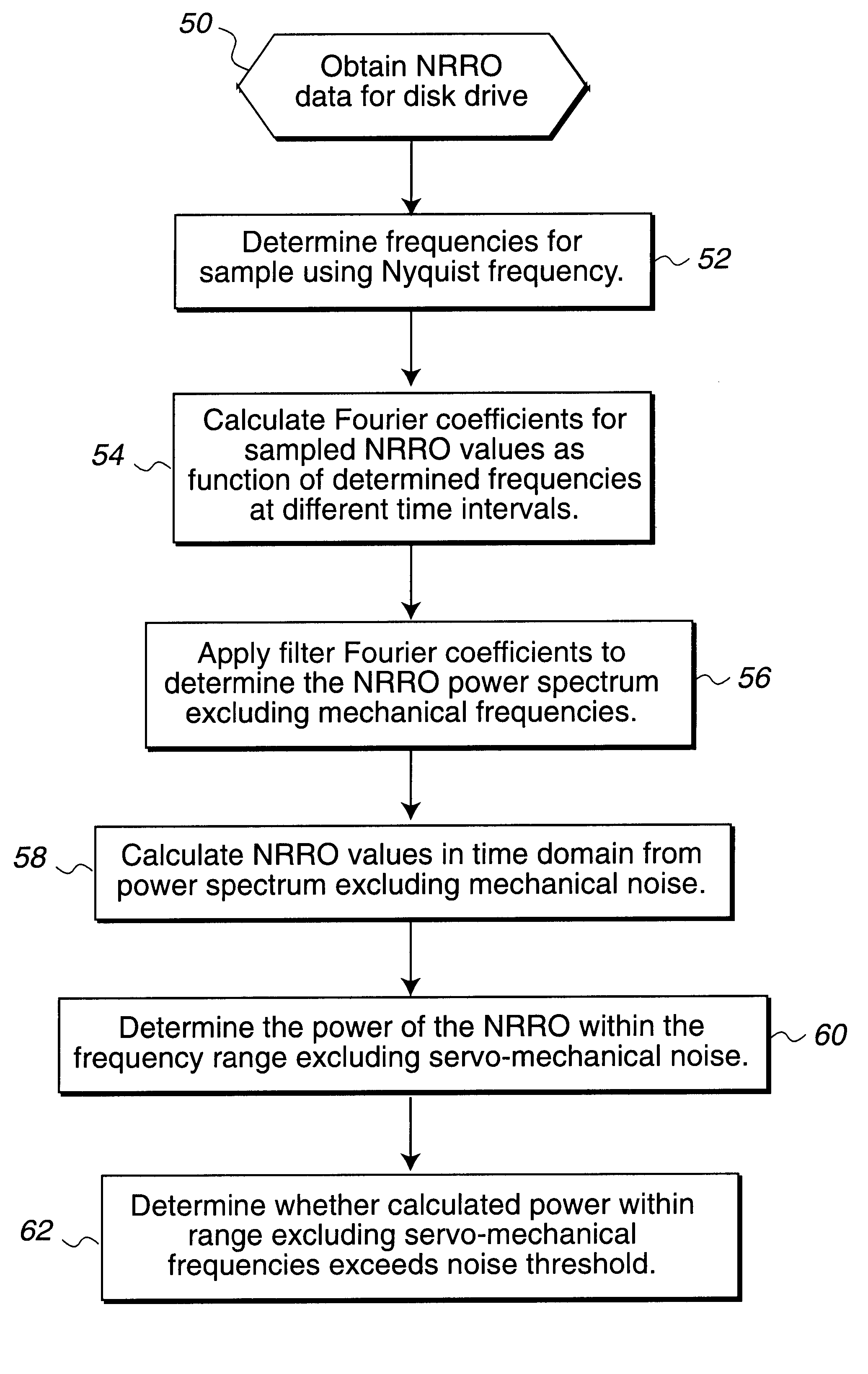
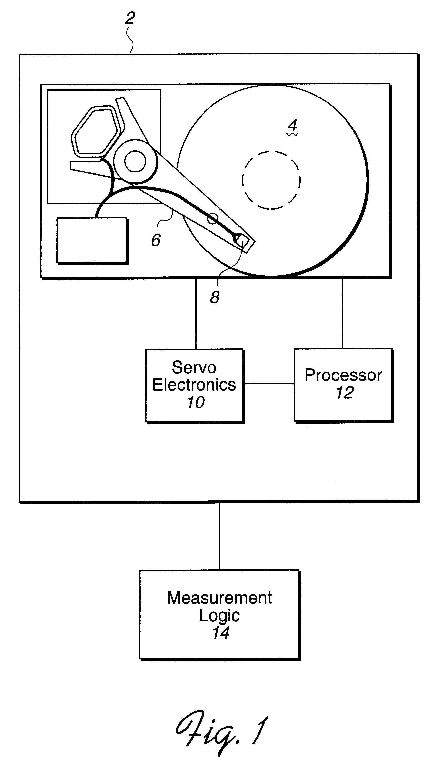
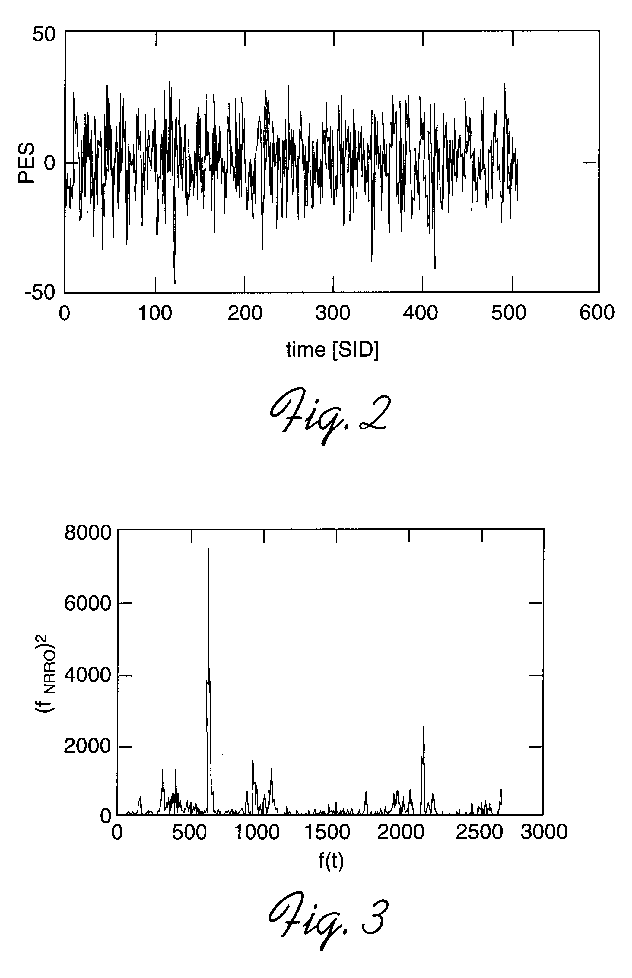
To overcome the limitations in the prior art described above, preferred embodiments disclose a system, method, and program for determining a value for non-mechanical noise within a disk drive system. The non-mechanical noise is likely related to instability in a head which reads data from a magnetic surface within the disk drive system. First, a sample of position error signals (PES) indicating non-repeatable runouts (NRRO) is provided from read operations within the disk drive system. Spectral analysis is then performed on the provided samples to calculate non-filtered power values for the NRRO values at different frequencies. A filtered power spectrum is determined within a frequency range excluding mechanical noise components. A filtered power value is calculated from the determined filtered power spectrum within the frequency range excluding mechanical noise.

The calculated filtered power value may be compared against a predetermined value to determine whether to reject the disk ...


PUM


Abstract

In summary, preferred embodiments disclose a system, method, and program for determining a value for non-mechanical noise within a disk drive system. The non-mechanical noise is likely related to instability in a head which reads data from a magnetic surface within the disk drive system. First, a sample of position error signals (PES) indicating non-repeatable runouts (NRRO) is provided from read operations within the disk drive system. Spectral analysis is then performed on the provided samples to calculate non-filtered power values for the NRRO values at different frequencies. A filtered power spectrum is determined within a frequency range excluding mechanical noise. A filtered power value is calculated from the determined filtered power spectrum within the frequency range excluding mechanical noise. The calculated filtered power value may be compared against a predetermined value to determine whether to reject the disk drive system on the grounds that there is too much non-mechanical noise or noise related to instabilities and defects in the MR head.

Description

1. Field of the InventionThe present invention relates to a method, system, and program for determining the magnetic center shift, or non-repeatable runout errors (NRRO), due to certain magnetic effects, absent mechanical noise.2. Description of the Related ArtComputer hard disk drives include one or more disks of magnetic storage medium and a disk drive head assembly to read and write data on the magnetic storage medium. Magnoresistive (MR) heads typically include a write element comprised of a thin film inductive head and a read element comprised of a sensor. Manufacturers often test disk drives to determine whether error rates within the disk drive exceed a threshold of acceptability and, therefore, require rejection of the particular disk drive unit. Errors in the ability of an MR head to properly read data from the storage surface can be caused, in part, by track misregistration due to head positioning irregularities on a rotating disk, track interference, and head (magnetic) d...

Claims


Application Information

Patent Timeline
IPC IPC(8): G11B5/596
CPCG11B5/59627
Inventor LAMBERTS, BERNDYU, MANTLE MAN-HON
Owner HITACHI GLOBAL STORAGE TECH NETHERLANDS BV
Why Eureka
Try Eureka