Method of producing a microwave filter

Inactive Publication Date: 2003-02-25
TELEFON AB LM ERICSSON (PUBL)
View PDF16 Cites 6 Cited by
  • Summary
  • Abstract
  • Description
  • Claims
  • Application Information

AI Technical Summary

Benefits of technology

By means of the invention, a microwave filter can therefore be constructed in a rapid and cost-effective manner. A great many plates with cutouts of different shape can be prefabricated, and, for production of a filter which is to have a certain desired characteristic, the plate which provides precisely the desired characteristic is selected as the first conductive plate. According to the invention, this plate is inserted between other pr

Problems solved by technology

Adjustment by means of trimming screws is a time-consuming and costly procedure, which is of course a disadvantage.
Furthermore, this technique makes it difficult to give the filter th

Method used


Image

  • Method of producing a microwave filter
  • Method of producing a microwave filter
  • Method of producing a microwave filter

Examples


Example

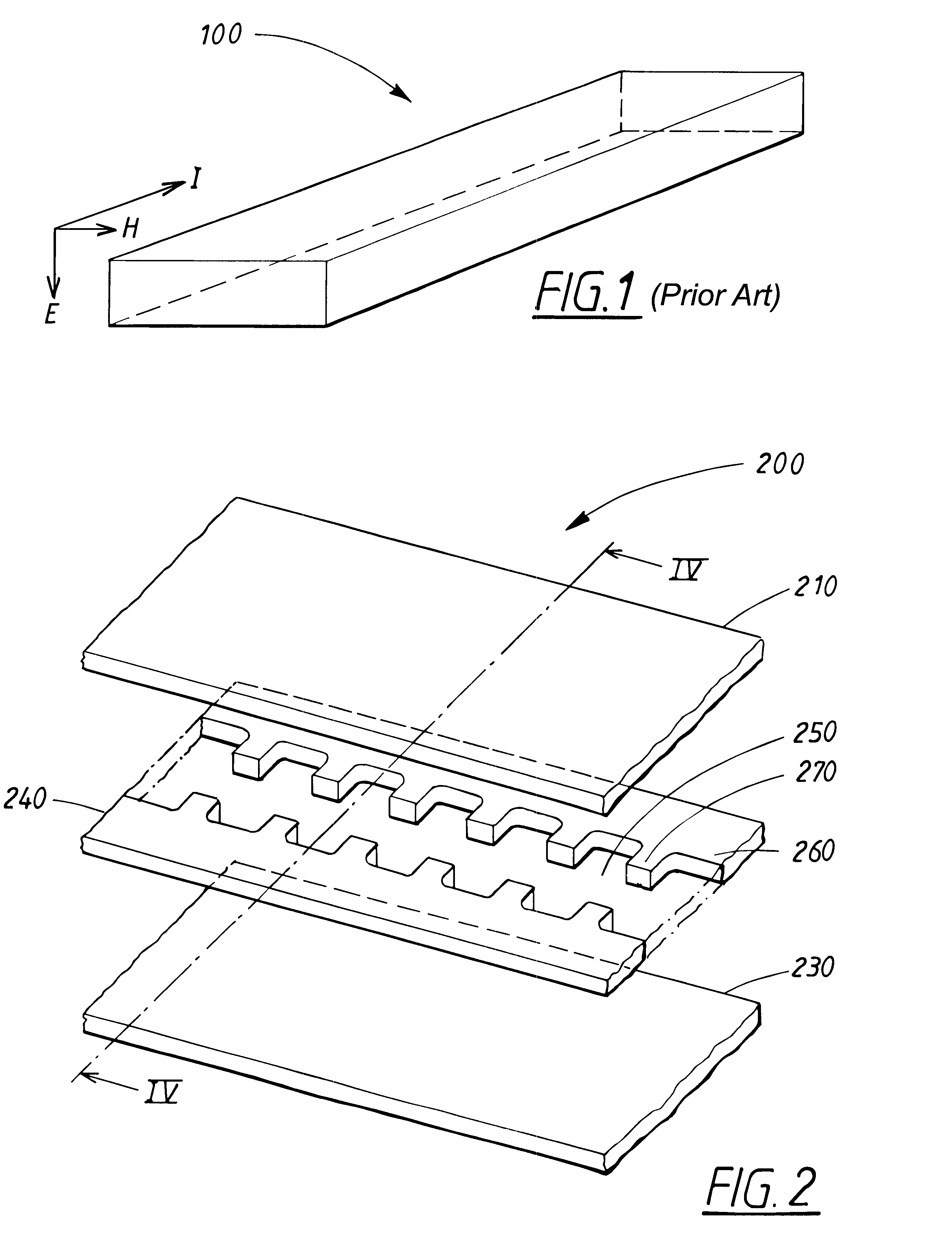
FIG. 1 shows a rectangular waveguide structure 100 of conventional type. The structure 100 is used to illustrate the reference directions which are to be used in the description below. An electrical signal is propagated in the waveguide structure 100 in a certain direction of propagation I which coincides with the longitudinal direction of the waveguide. In a cross section at right angles through the direction of propagation of the waveguide, the electrical signal has an E-field and an H-field in a manner well known to the person skilled in the art.

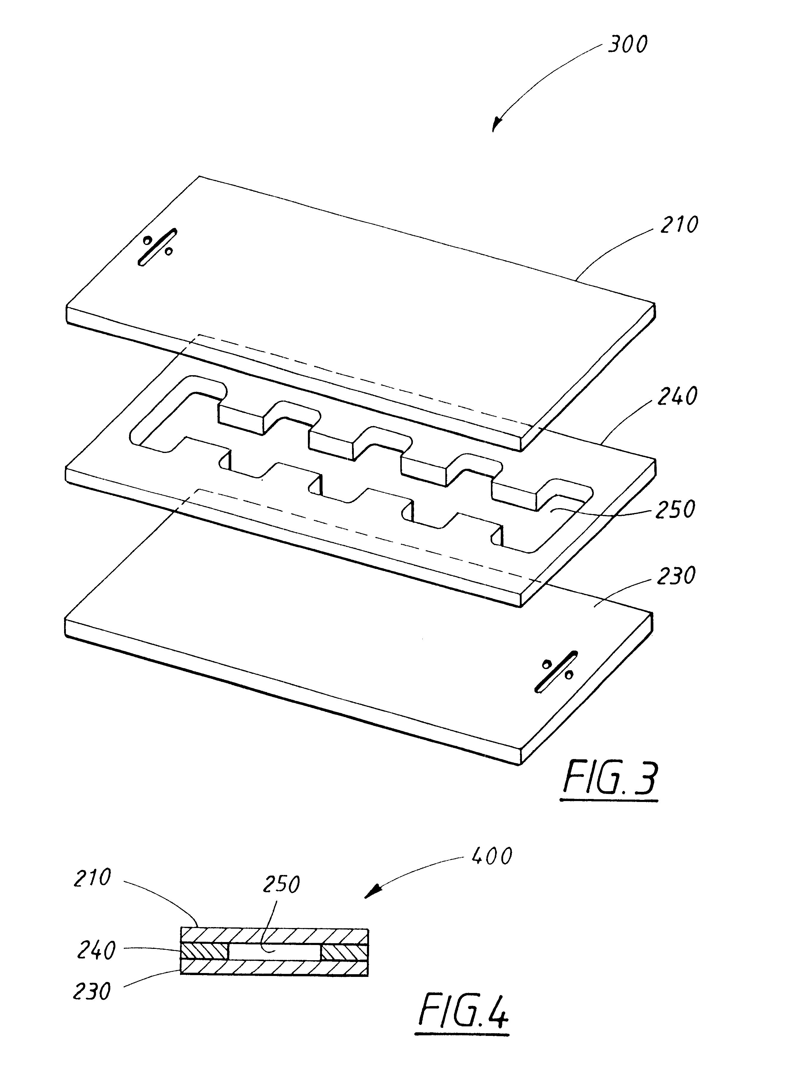
FIG. 2 shows an exploded diagram of a portion in the longitudinal direction of a filter produced by means of a method according to the invention. In a first electrically conductive plate 240 with a first and a second main plane of extent, a cutout 250 has been made, which goes right through the plate. This cutout 250 can be made in a great many different ways. The cutout is suitably made by means of punching, but, among other possible met...


PUM

PropertyMeasurementUnit
Fractionaaaaaaaaaa
Thicknessaaaaaaaaaa
Electrical conductivityaaaaaaaaaa

Abstract

The invention relates to a method for producing a microwave filter (700), comprising making at least one through-cutout (750) in a first electrically conductive plate (740) shaped as a rectangle, with a short side and a long side, inserting the first plate (740) between a second (710) and a third (730) electrically conductive plate (710), the first plate being arranged parallel to the second and the third plate, making electrical connections (794, 795) between said three plates for interconnecting those edge surfaces on the plates which coincide with the direction of propagation of the electrical signals, as a result of which a space comprising one or more cavities is formed. The first plate (740) is arranged so that the extent of its short side coincides with the E-field of the microwave signals when they propagate in the filter (700), and the extent of its long side coincides with the direction of propagation of the electrical signals.

Description

TECHNICAL FIELDThe present invention relates to a method of producing a filter for electromagnetic microwave signals.The invention also relates to a filter for electromagnetic microwave signals. The filter comprises a first, second and third conductive plate, the first plate being arranged between the other two, and the first plate having a through-cutout. The plates are connected to one another by electrically conductive connections which interconnect those edge surfaces on the plates which coincide with the direction of propagation of the electrical signals, as a result of which a space is formed, which, in the direction of propagation of the signals, is enclosed by electrically conductive surfaces.BACKGROUND ARTIn the production of microwave filters, it is usual to make use of, for example, waveguide structures which are provided with what are known as trimming screws. By means of the trimming screws, the waveguide structure is adjusted so that it has the desired filter character...

Claims


Application Information

Patent Timeline
IPC IPC(8): H01P11/00
CPCH01P11/007Y10T29/4902Y10T29/49016
Inventor SNYGG, GORANJOHANSSON, SUNESVENSSON, BENGT
Owner TELEFON AB LM ERICSSON (PUBL)
Why Eureka
Try Eureka