Hand truck with electrically operated lifting platform

a lifting platform and hand truck technology, applied in the field of hand trucks, can solve the problems of high installation cost, low speed and inconvenient working procedure for conveying relatively small cargo, high cost of conventional hydraulic pallet trucks, etc., and achieve the effect of simple structure and lower cos

Inactive Publication Date: 2003-03-11
JUNG DONG HUN
View PDF10 Cites 101 Cited by
  • Summary
  • Abstract
  • Description
  • Claims
  • Application Information

AI Technical Summary

Benefits of technology

Accordingly, the present invention has been made keeping in mind the above problems occurring in the prior art, and an object of the present invention is to provide a hand truck with an electrically operated lifting platform, in which a lifting platform is attached to a frame provided at its lower ends with wheels to be moved selectively upward and downward, and a platform moving unit is situated in the lifting platform to be controlled by a drive control unit, thereby having a simple structure, being manufactured at lower costs and obtaining the same output as that of a conventional hand truck.

Problems solved by technology

However, this kind of arrangement necessitates high installation costs, has lower rapidity and inconvenient working procedure to convey relatively small cargo, and requires to use separate conveying means and lifting means in an area outside of the area over which rails are extended.
However, the conventional hydraulic pallet truck is expensive and relatively heavy because its hydraulic drive unit and control unit should be provided, and causes inconvenience to a user because its forks cannot be brought into contact with the ground owing to the large mounting space of hydraulic drive unit and should be supported by a support.
However, the conventional hand truck has inferior safety because their screw shafts are exposed to the outside, and is costly because its rapid ascent control unit and drive unit are expensive.

Method used


Image

  • Hand truck with electrically operated lifting platform
  • Hand truck with electrically operated lifting platform
  • Hand truck with electrically operated lifting platform

Examples


Embodiment Construction

Reference now should be made to the drawings, in which the same reference numerals are used throughout the different drawings to designate the same or similar components.

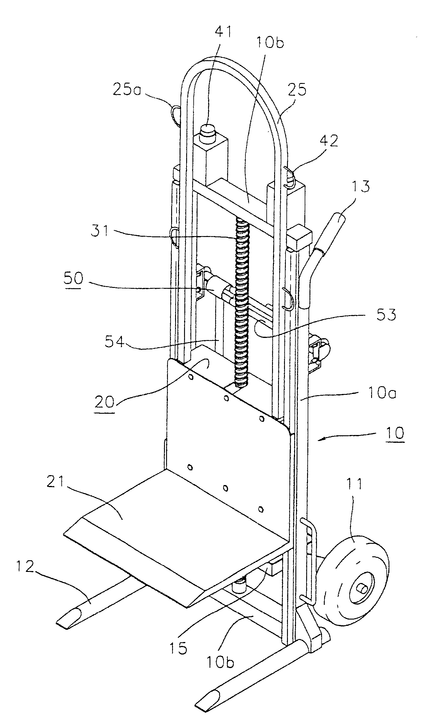
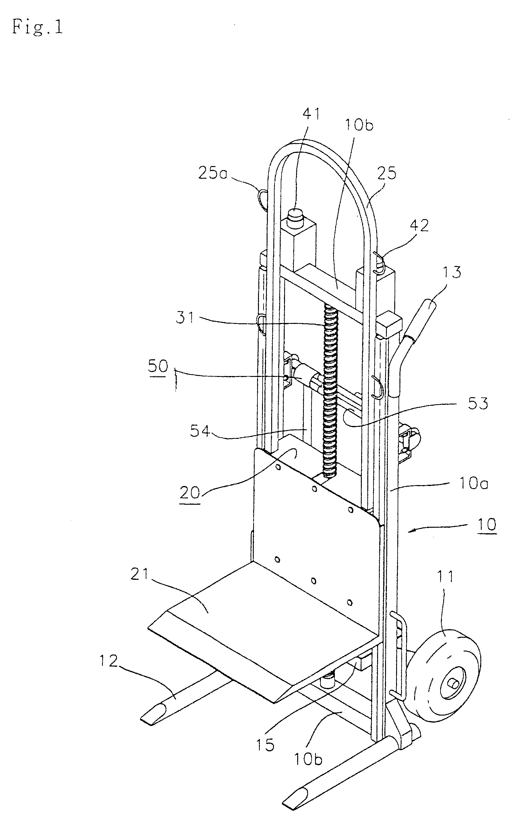
As shown in FIGS. 1 and 2, a lifting platform 20 is attached to a frame 10, which is provided at both sides of the frame 10 with two wheels 11 and has a form of a carrier. A platform moving unit is situated in the lifting platform 20 and controlled by a control unit.

When a switch is manipulated, the application of electricity to the platform moving unit is controlled by the control unit, and the lifting platform 20 is lifted up and lowered down along both sides of the frame 10 in accordance with the control of the control unit, thereby moving cargo selectively upward and downward.

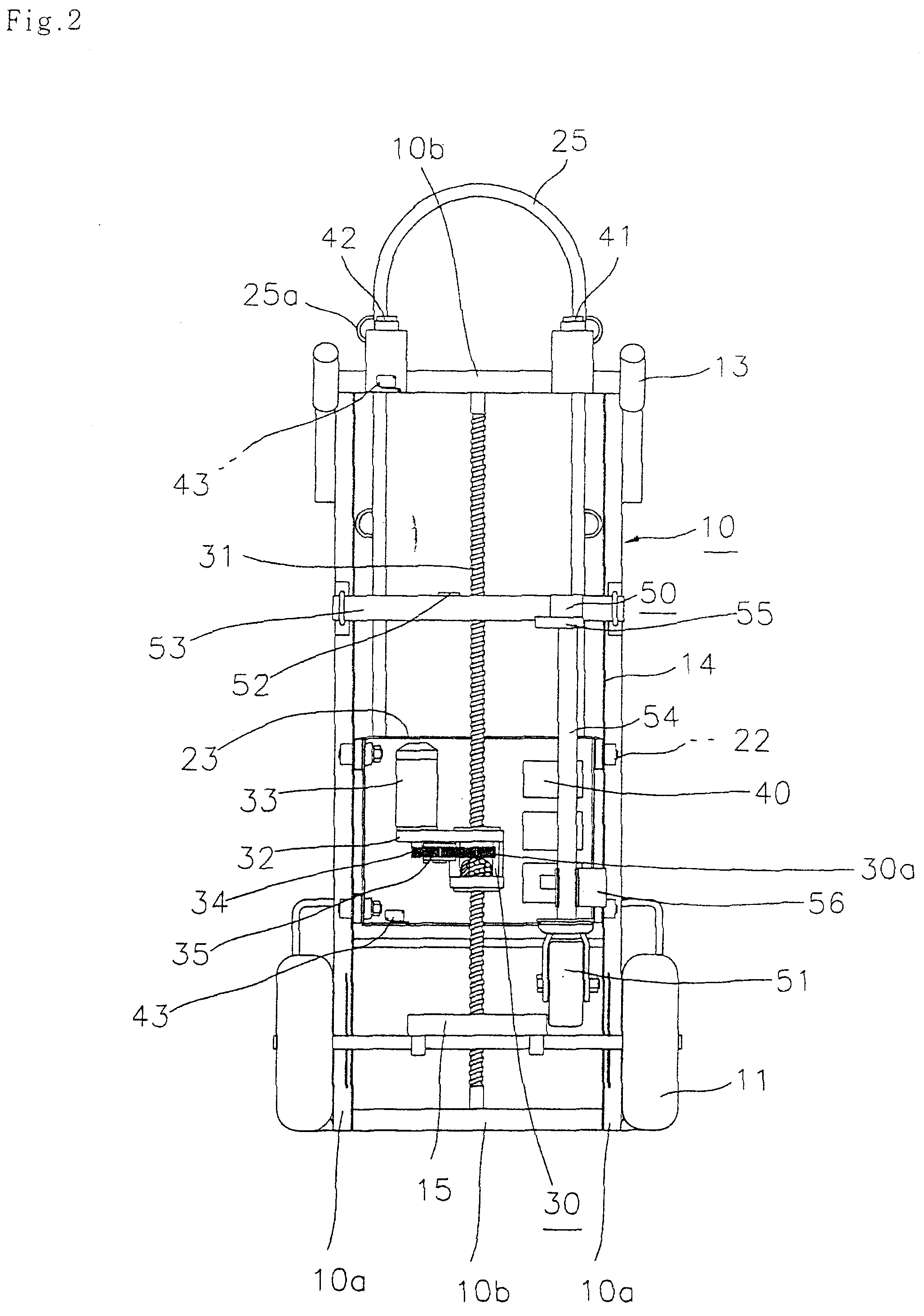
The frame 10, as depicted in FIGS. 1 to 3, is constructed in such a way that two spaced vertical rods 10a having an equal height are connected by two crosspieces, respectively, at upper and lower ends, two stabilizing bars 12 are forwardly ...


PUM


Abstract

This invention relates to a hand truck with an electrically operated lifting platform. The hand truck includes a frame on both sides of which two guide rails are formed. The frame is provided with a screw shaft vertically supported on the frame to be vertically moved, one or more stabilizing bars forwardly extended from the frame, and two wheels rotatably attached to the rear portion of the frame. A lifting platform is guided by the guide rails and engaged with the screw shaft. A platform moving unit is comprised of a first drive motor for providing rotating force. The platform is situated in the lifting platform to allow the lifting platform to be moved selectively upward and downward along the screw shaft by the operation of the first drive motor. A control unit is electrically and controllably connected to the first drive motor and a power source.

Description

BACKGROUND OF THE INVENTION1. Field of the InventionThe present invention relates generally to hand trucks for facilitating the conveying, loading and unloading of cargo, and more particularly to a hand truck with an electrically operated lifting platform, which is capable of lowering the costs of manufacture and maintenance and improving convenience in handling and safety.2. Description of the Prior ArtIn general, in order to convey, load and unload massive cargo, a plurality of pillars and rails are arranged in a factory and a hoist is mounted so as to be moved along the rails.However, this kind of arrangement necessitates high installation costs, has lower rapidity and inconvenient working procedure to convey relatively small cargo, and requires to use separate conveying means and lifting means in an area outside of the area over which rails are extended.On the meantime, a hydraulic pallet truck is proposed so as to convey, load or unload cargo to which the hoist cannot be applie...

Claims


Application Information

Patent Timeline
Patent Type & Authority Patents(United States)
IPC IPC(8): B62B1/00B62B5/02B62B1/14
CPCB62B1/002B62B5/028B62B1/14B62B2203/10
Inventor KIM, JIN YU
Owner JUNG DONG HUN
Why Eureka
Try Eureka