Cellular hydrostatic fluid bearing, and a method of making it

a technology of fluid bearings and hydrostatic fluid, which is applied in the direction of transportation and packaging, mechanical equipment, other domestic objects, etc., can solve the problems of difficult to machine such cells, difficult to machining, and still relatively little used in rocket engine turbopumps

Inactive Publication Date: 2003-03-18
SN DETUDE & DE CONSTR DE MOTEURS DAVIATION S N E C M A
View PDF24 Cites 4 Cited by
  • Summary
  • Abstract
  • Description
  • Claims
  • Application Information

AI Technical Summary

Benefits of technology

The present invention seeks to remedy the above-mentioned drawbacks and to provide a cellular hydrostatic fluid bearing in more convenient manner and minimizing the risks of failure in the event of shaft-bearing contacts.
Thus, the fluid bearing of the invention presents a thickness of a layer of composite material on its inside surface that can accommodate a large amount of wear therein without running the risk of irremediable damage to the shaft or the bearing in the event of shaft-bearing contacts, which also makes it possible to pass through transient stages without auxiliary means for providing pressure.
The method of the invention for manufacturing a hydrostatic bearing thus makes it possible to make the inner portion of the stator that is to receive a rotary shaft from a plane metal structure that enables a thick layer of self-lubricating composite material to be formed and that makes it easier to machine the cells.

Problems solved by technology

Nevertheless, they are still relatively little used in rocket engine turbopumps.
Since the inside surface of the stator is cylindrical, it is quite difficult to machine such cells.
Machining is particularly difficult when the diameter of the stator is small.
Such an auxiliary device contributes to making the pump apparatus as a whole heavier and increases the risk of failure.
. . ) that occur during the operation of such pumps, the fluid pressure feed to the bearings as taken from the outlet of the pump is not yet or is no longer at a level which is sufficient to ensure that the rotor is levitated.
Unfortunately, such treatment of the inside surface of the bearing presents various difficulties, in particular concerning the thickness of such a coating layer, which thickness is generally less than 50 micrometers (.mu.m), and also concerning its uniformity.
The small thicknesses contained do not make it possible to accommodate a large number of transient stages without damaging the shaft and the bearings.

Method used


Image

  • Cellular hydrostatic fluid bearing, and a method of making it
  • Cellular hydrostatic fluid bearing, and a method of making it
  • Cellular hydrostatic fluid bearing, and a method of making it

Examples


Embodiment Construction

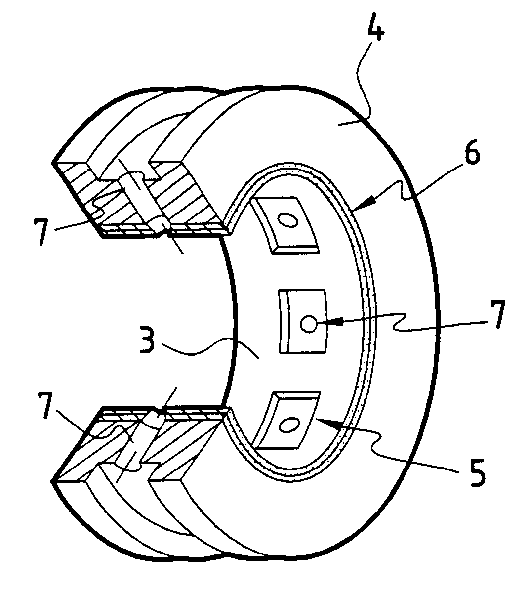
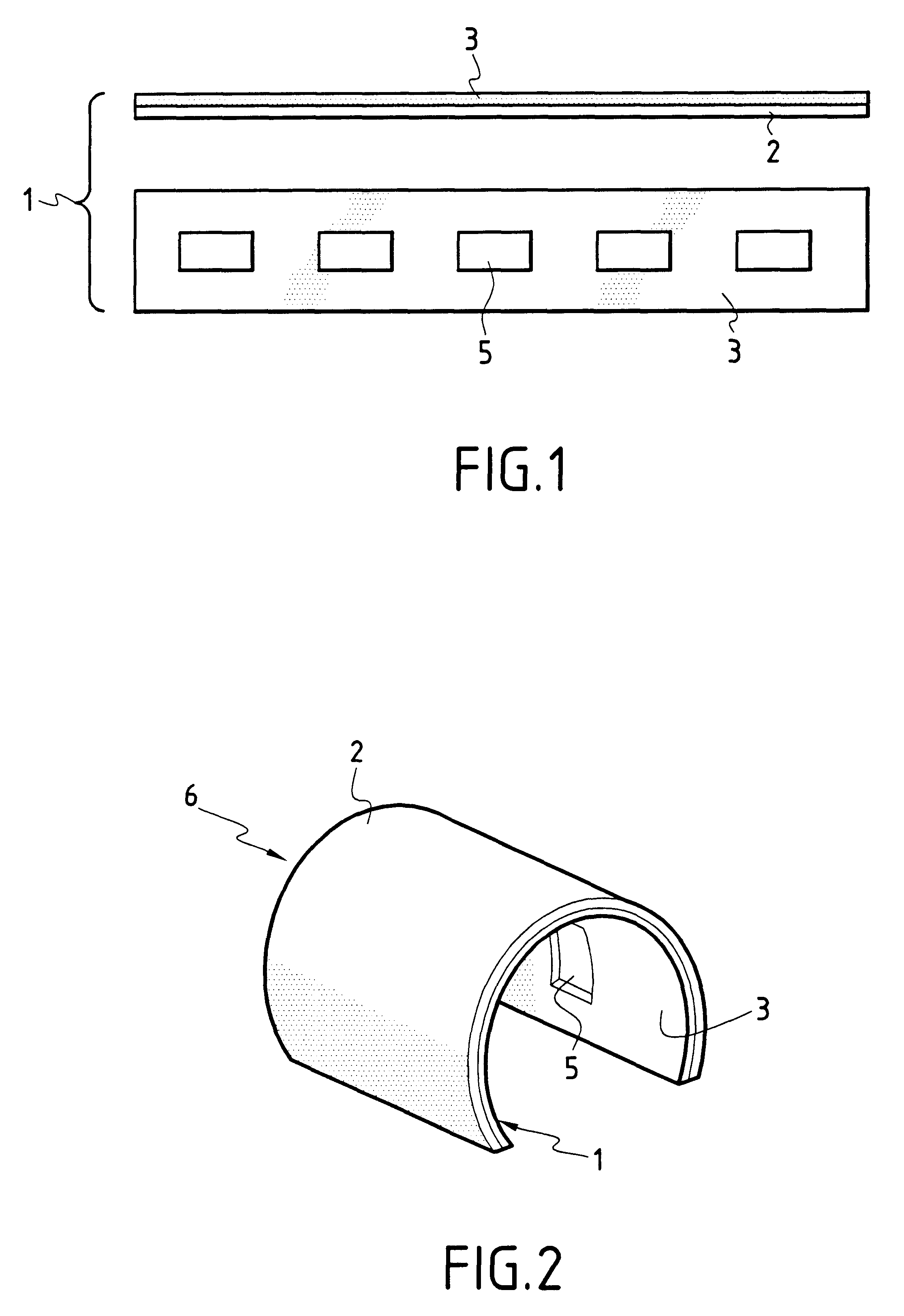
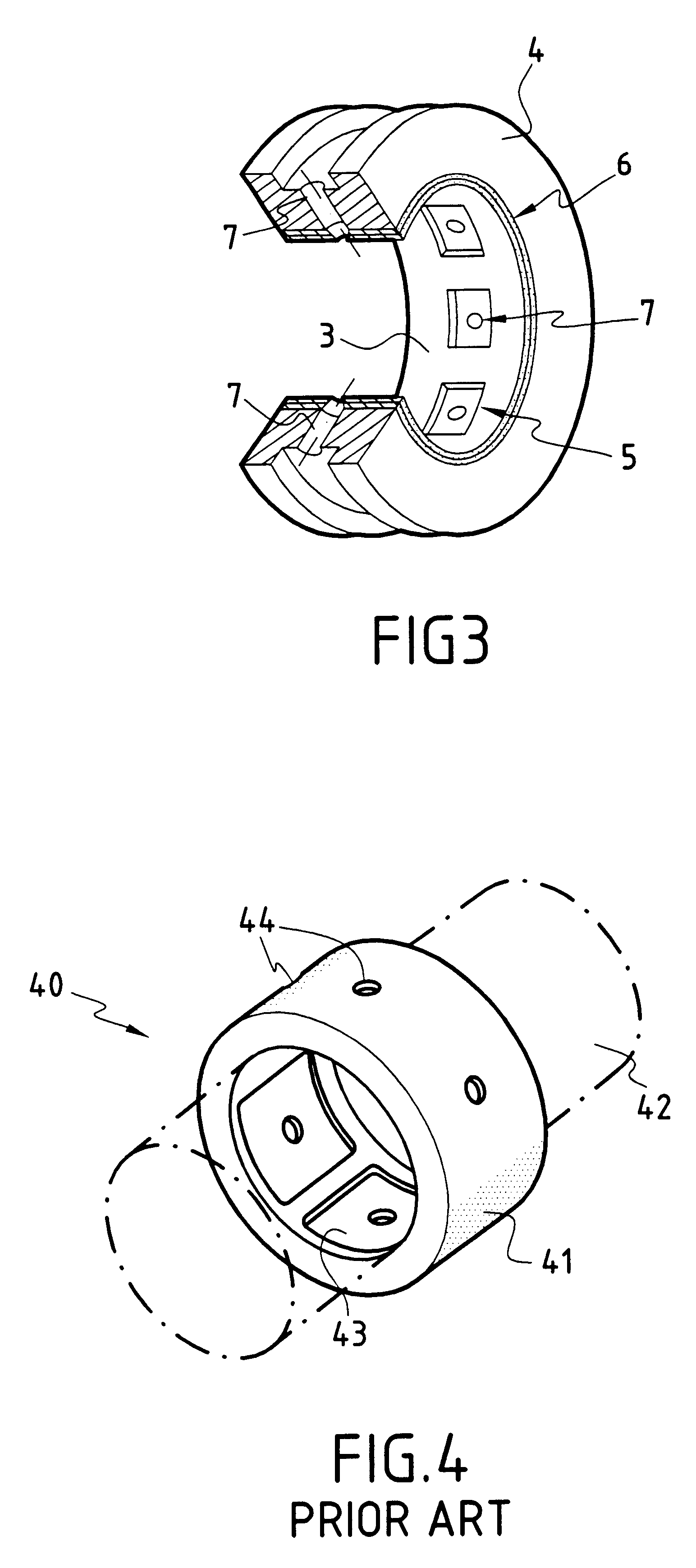
FIG. 3 shows a hydrostatic fluid bearing constituting an embodiment of the invention. The bearing of the invention comprises a solid stator 4 of cylindrical shape having a split ring 6 on its inside surface which is held in place by compression inside the stator 4. The ring 6 has a first thickness constituted by a metal plate 2 which is in contact with the inside surface of the stator 4, and a second thickness formed by a layer of self-lubricating composite material 3 which defines the inside surface of the bearing that is to support and levitate a rotary shaft (not shown). The layer of composite material 3 has cells 5 at regular intervals over the inside surface of the bearing. Each cell 5 presents an orifice 7 which passes through the thickness of the stator 4 and the metal plate 2. The orifices 7 enable the cells 5 of the bearing to be fed with fluid under pressure to provide the mechanism for levitating the rotary shaft that is specific to hydrostatic bearings.

The hydrostatic be...


PUM

PropertyMeasurementUnit
thicknessaaaaaaaaaa
thicknessaaaaaaaaaa
thicknessaaaaaaaaaa

Abstract

The hydrostatic fluid bearing comprises a cylindrical stator having orifices for introducing a fluid under pressure, on its inside surface the stator has a split ring constituted by an assembly comprising a plane metal plate and a layer of self-lubricating composite material. The layer of composite material has cells for surrounding orifices for introducing fluid under pressure, once the assembly has been put into place inside the stator.

Description

The present invention relates to the field of cellular hydrostatic fluid bearings for supporting rotary shafts, in particular in rocket engine turbopumps for pressurizing fluid.PRIOR ARTCellular hydrostatic fluid bearings are in widespread use in numerous industrial applications, in particular where high loads are involved or which require high speed, or great precision, or long lifetime. Nevertheless, they are still relatively little used in rocket engine turbopumps.FIG. 4 shows the structure of a conventional hydrostatic bearing 40 comprising an annular bearing stator 41 in which a rotor 42 constituting the shaft of a turbopump is received. When the turbopump is in operation, the rotor 42 is held in suspension by a thin layer of fluid introduced under pressure through orifices 44 in cells 43 of the bearing stator 41. The cells 43 are machined directly in the material of the stator 41. Since the inside surface of the stator is cylindrical, it is quite difficult to machine such cell...

Claims


Application Information

Patent Timeline
Patent Type & Authority Patents(United States)
IPC IPC(8): F16C32/06
CPCF16C32/0659F16C32/0662Y10T29/49655Y10T29/49671Y10T29/49677Y10T29/49696Y10T29/49639F16C32/0655F16C32/0685F16C43/02F16C2326/43
Inventor BRUNE, CLAUDEFAYOLLE, PATRICEMOELLO, REGISFRECHON, GILLES
Owner SN DETUDE & DE CONSTR DE MOTEURS DAVIATION S N E C M A
Why Eureka
Try Eureka