System for active regulation of the air/gas ratio of a burner including a differential pressure measuring system

a technology of active regulation and air/gas ratio, which is applied in the field of active regulation of the air/gas ratio of the burner, can solve the problems of extreme cost, inability to use the apparatus where the total cost of manufacture must remain relatively low, and subject to thermal drift and long-term drift, so as to achieve the effect of simple and less cos

Inactive Publication Date: 2003-03-18
A THEOBALD
View PDF7 Cites 65 Cited by
  • Summary
  • Abstract
  • Description
  • Claims
  • Application Information

AI Technical Summary

Benefits of technology

In a first embodiment of the system for regulating the air/gas ratio, it is possible to use two differential pressure measuring systems according to the invention to measure the flowrate of air in the air pipe and the difference between the air and gas pressures in the air pipe and in the gas pipe, respectively, each of w

Problems solved by technology

Differential pressure sensors of this kind exist, but they are extremely costly and therefore cannot be used in apparatus where the total cost of manufacture must remain relatively low, for example in a system for regulating the air/gas ratio of a burner, for example the burner of a boiler for producing domestic hot water and/or central heating hot water.
Also, there are differential pressure sensors which are relatively inexpensive but which are subject to thermal drift and long-term drift which often exceed a few percent.
The output signal of such sensors can therefore not be used directly for a

Method used


Image

  • System for active regulation of the air/gas ratio of a burner including a differential pressure measuring system
  • System for active regulation of the air/gas ratio of a burner including a differential pressure measuring system
  • System for active regulation of the air/gas ratio of a burner including a differential pressure measuring system

Examples


first embodiment

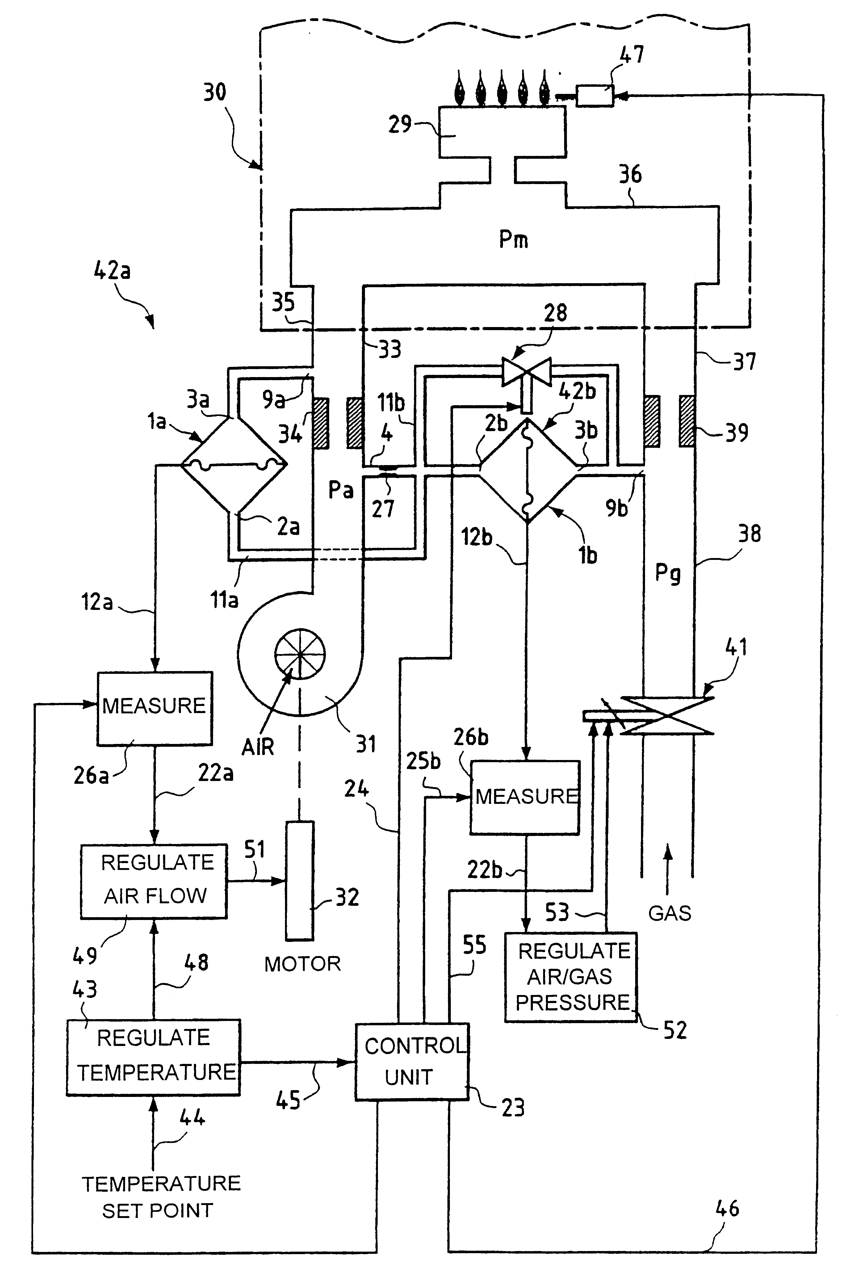
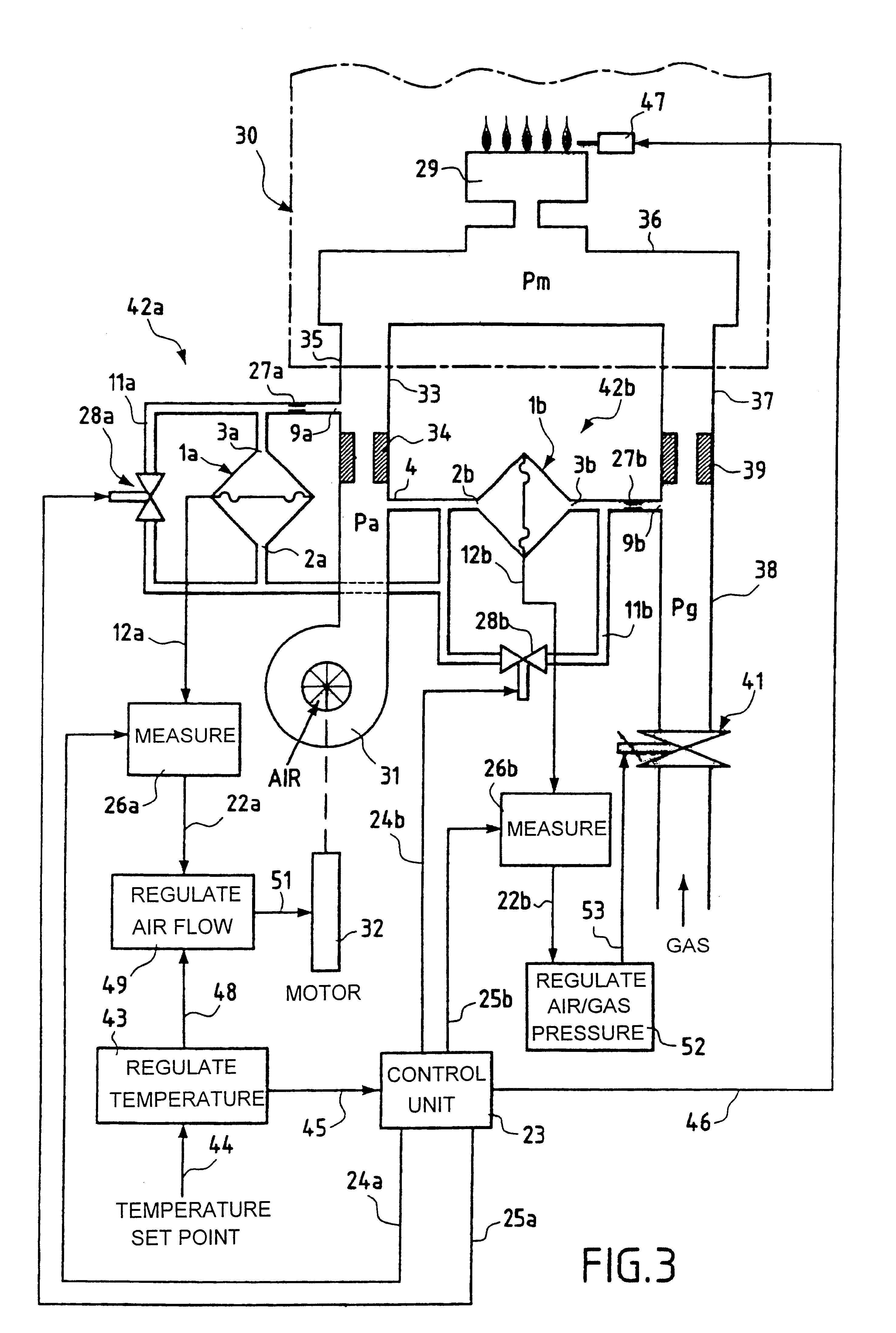
FIG. 3 shows one example of a system constituting the invention for regulating the air / gas ratio of a burner 29, for example the burner of a boiler 30.

Referring to FIG. 3, a fan 31 is driven by a variable speed electric motor 32 and is connected by a pipe 33 containing a calibrated air diaphragm 34 to a first input 35 of an air / gas mixer 36 upstream of the burner 29. Although the air / gas mixer 36 is shown here as a component separate from the burner 29, it can instead be integrated into the burner, as is well-known in the art. A gas supply pipe 38 connected to a second input 57 of the mixer 36 contains a calibrated gas diaphragm 39 and a proportional valve 41 upstream of that diaphragm whose inlet side is connected to a compressed fuel gas supply (not shown), for example to a compressed fuel gas supply main. The proportional valve 41 is used to vary the gas pressure Pg in the pipe 38 upstream of the calibrated orifice 39 and consequently the quantity of gas fed to the mixer 36.

In FI...

second embodiment

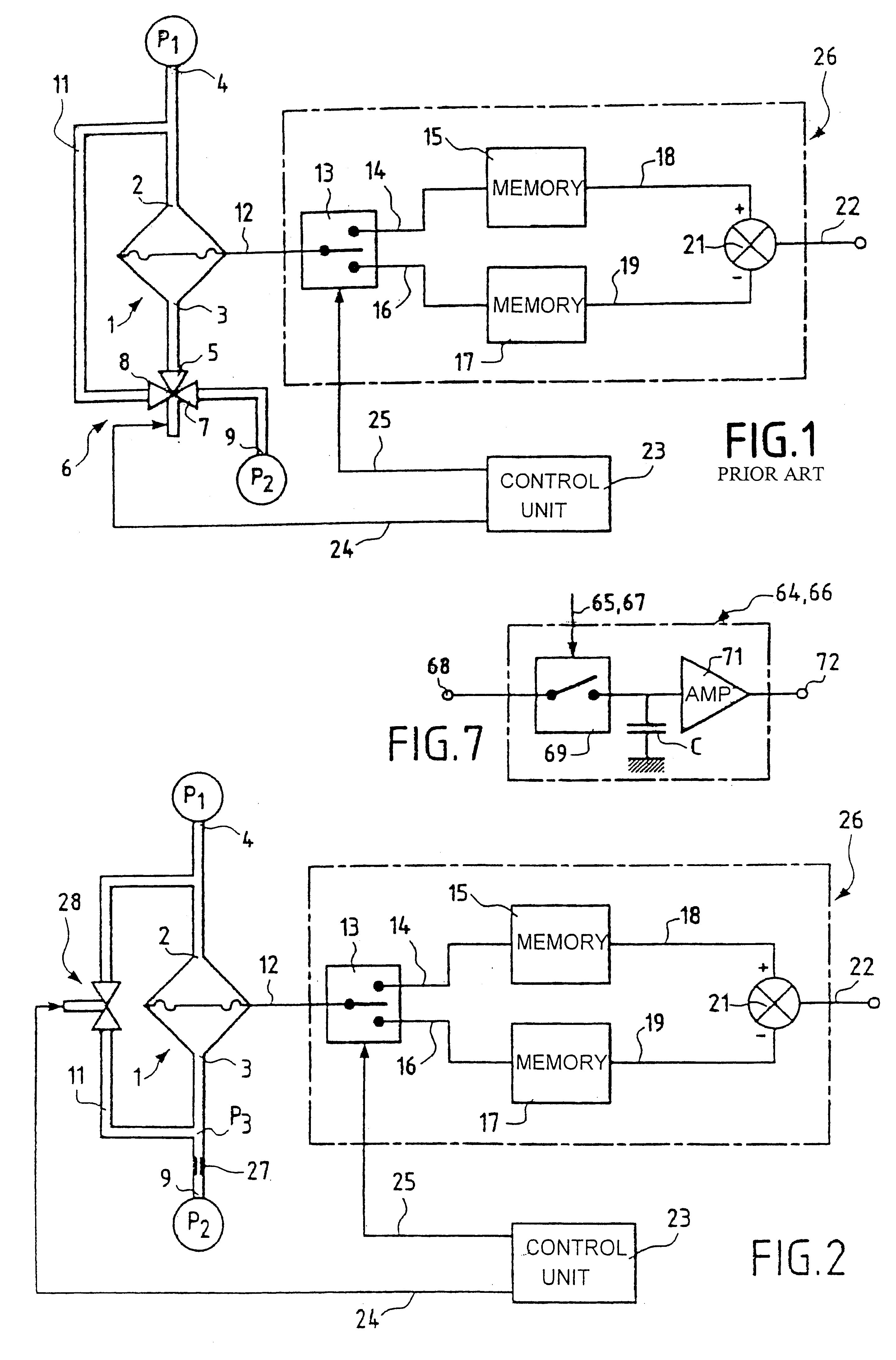
FIG. 4 shows a system for regulating the air / gas ratio of a burner, including a single calibrated throttling orifice and a single 2-channel valve for calibrating two differential pressure sensors. In FIG. 4, components of the air / gas ratio regulator system which are identical to or have the same function as those of the air / gas ratio regulator system shown in FIG. 3 are designated by the same reference numbers and are not described again in detail. The air / gas ratio regulator system shown in FIG. 4 differs from that shown in FIG. 3 essentially in that it has only one calibrated throttling orifice 27, which is located in the common pressure port 4, and only one 2-channel valve 28. One of the two channels of the valve 28 is connected directly to the inlet orifices 2a and 2b of the sensors 1a and 1b and via the calibrated throttling orifice 27 to the pressure port 4. The other channel of the valve 28 is connected to a pressure port 54 connected to the air pipe 33 downstream of the air ...


PUM


Abstract

The system for active regulation of the air/gas ratio of a burner comprises one or two differential pressure measuring systems each of which has a differential pressure sensor with two inlet orifices. The orifices are respectively connected to pressure ports in one of which there is a calibrated throttling orifice. The regulator system comprises a 2-channel valve which, when closed, isolates the two inlet orifices from each other, and, when open, connects them to each other. A measurement circuit is provided and has memory means for storing at least two values of the output signal of the sensors, a control unit for switching the valve and controlling the storage of a first value of an output signal of the sensor in the memory means when the valve is closed and the storage of a second value of the output signal of the sensor when the valve is open, and subtractor means for calculating the difference between the two stored values of the output signal of the sensor and thereby eliminating any drift. In a preferred variant, the regulator system includes only one differential pressure measuring system.

Description

The present invention relates to a system for active regulation of the air / gas ratio of a mixture of air and fuel gas fed to a burner, using at least one differential pressure measuring system.In many kinds of apparatus and installations in which one or more liquid or gaseous fluids circulate, it is often necessary to be able to measure accurately the flowrate of a working fluid and / or the pressure difference between two different working fluids in order to monitor and / or regulate and / or adjust a process. A differential pressure system is usually employed for this purpose, comprising a differential pressure sensor with two inlets connected to respective pressure ports. In the case of measuring the flowrate of a fluid, the two pressure ports are on respective opposite sides of a diaphragm placed in the pipe in which the fluid flows. In the case of measuring the pressure difference between two different fluids, the two pressure ports are connected to respective pipes in which the two ...

Claims


Application Information

Patent Timeline
IPC IPC(8): F23N5/24F23N1/02F23N5/18
CPCF23N5/188F23N5/242F23N1/02F23N2900/05181F23N2033/08F23N2035/16F23N2025/04F23N2225/04F23N2233/08F23N2235/16
Inventor PECHOUX, CHRISTOPHE
Owner A THEOBALD
Why Eureka
Try Eureka