

Planar antenna
a technology of antennas and antenna supports, applied in the direction of antenna supports/mountings, radiating element structural forms, electrical devices, etc., can solve the problems of reducing bandwidth, reducing efficiency, and reducing bandwidth
Inactive Publication Date: 2003-03-25
PULSE FINLAND
View PDF14 Cites 117 Cited by
- Summary
- Abstract
- Description
- Claims
- Application Information
AI Technical Summary
Benefits of technology
An advantage of the invention is that it achieves a significant increase in the antenna bandwidth without increasing the size of the antenna. Another advantage of the invention is that the structure according to it is simple and the increase in the manufacturing cost is relatively low.
Problems solved by technology
For example, decreasing the height of a PIFA, i.e. bringing the radiating plane and ground plane closer to each other, markedly decreases the bandwidth and degrades the efficiency.
Likewise, reducing the antenna in the directions of width and length by making the physical lengths of the elements smaller than their electrical lengths decreases the bandwidth and especially degrades the efficiency.
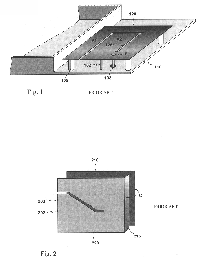
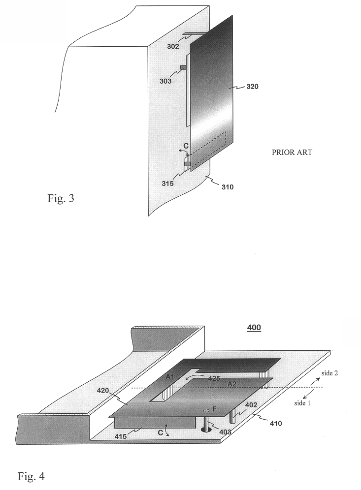
The disadvantage of structures like the one described in FIG. 1 is that the tendency towards smaller antennas for compact mobile stations may degrade the electrical characteristics of an antenna too much; the bandwidth of the higher resonance band may be insufficient, for example.
Method used
View moreImage
Smart ImageViewing Examples

Examples
second embodiment
FIG. 5 shows the invention,
third embodiment
FIG. 6 shows the invention,
FIG. 7 shows a fourth embodiment of the invention,
FIG. 8 shows an example of the characteristics of an antenna according to the invention, and
FIG. 9 shows an example of a mobile station equipped with an antenna according to the invention.
Login to View More PUM
 Abstract
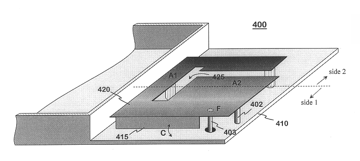
The invention relates to an antenna structure (400) to be placed inside in particular small radio apparatus. A conventional PIFA-type structure is extended by arranging a structural part (415) adding to the capacitance between the radiating plane (420) and ground plane (410) relatively close to the feed point (F) of the antenna. The structural component may be a projection extending from the radiating plane towards the ground plane or vice versa. An advantage of the invention is that it achieves a significant increase in the antenna bandwidth without increasing the size of the antenna. Another advantage of the invention is that the structure according to it is simple and the increase in the manufacturing costs is relatively low.
Description
This application claims priority from Finland Application No. 19992356, entitled "Planar Antenna," filed on Nov. 1, 2000, the disclosure of which is hereby incorporated by reference in its entirety.1. Field of the InventionThe invention relates in particular to a planar antenna structure installable inside small-sized radio apparatus.2. Description of the Related ArtIn portable radio apparatus it is very desirable that the antenna be placed inside the covers of the apparatus, for a protruding antenna is impractical. In modem mobile stations, for example, the internal antenna naturally has to be small in size. This requirement is further emphasized as mobile stations become smaller and smaller. Furthermore, in dual-band antennas the higher operating band at least should be relatively wide, especially if the apparatus in question is meant to function in more than one system utilizing the 1.7-2 GHz band.When aiming at a small-sized antenna the most common solution is to use a PIFA (pla...
Claims
Login to View More Application Information
Patent Timeline
 IPC IPC(8): H01Q1/24H01Q9/04
CPCH01Q1/243H01Q9/0442H01Q9/0421
InventorISOHATALA, ANNETARVAS, SUVIANNAMAA, PETTERI
OwnerPULSE FINLAND