Broadband antenna structure

a broadband antenna and antenna structure technology, applied in the direction of radiating element structural forms, resonant antennas, substantially flat resonant elements, etc., can solve the problems of limiting the frequency response and the frequency limitation of baluns in antenna structures has now become a problem, so as to increase the frequency response of antenna structures and increase the number of frequency bands

Inactive Publication Date: 2003-03-25
LUCENT TECH INC
View PDF23 Cites 43 Cited by
  • Summary
  • Abstract
  • Description
  • Claims
  • Application Information

AI Technical Summary

Benefits of technology

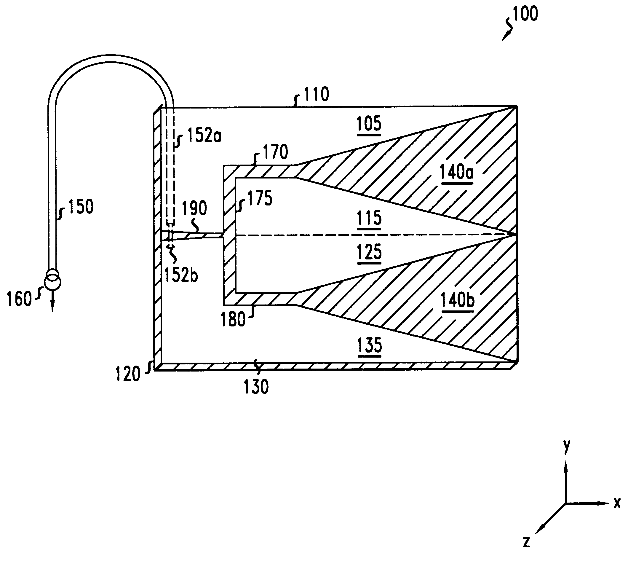
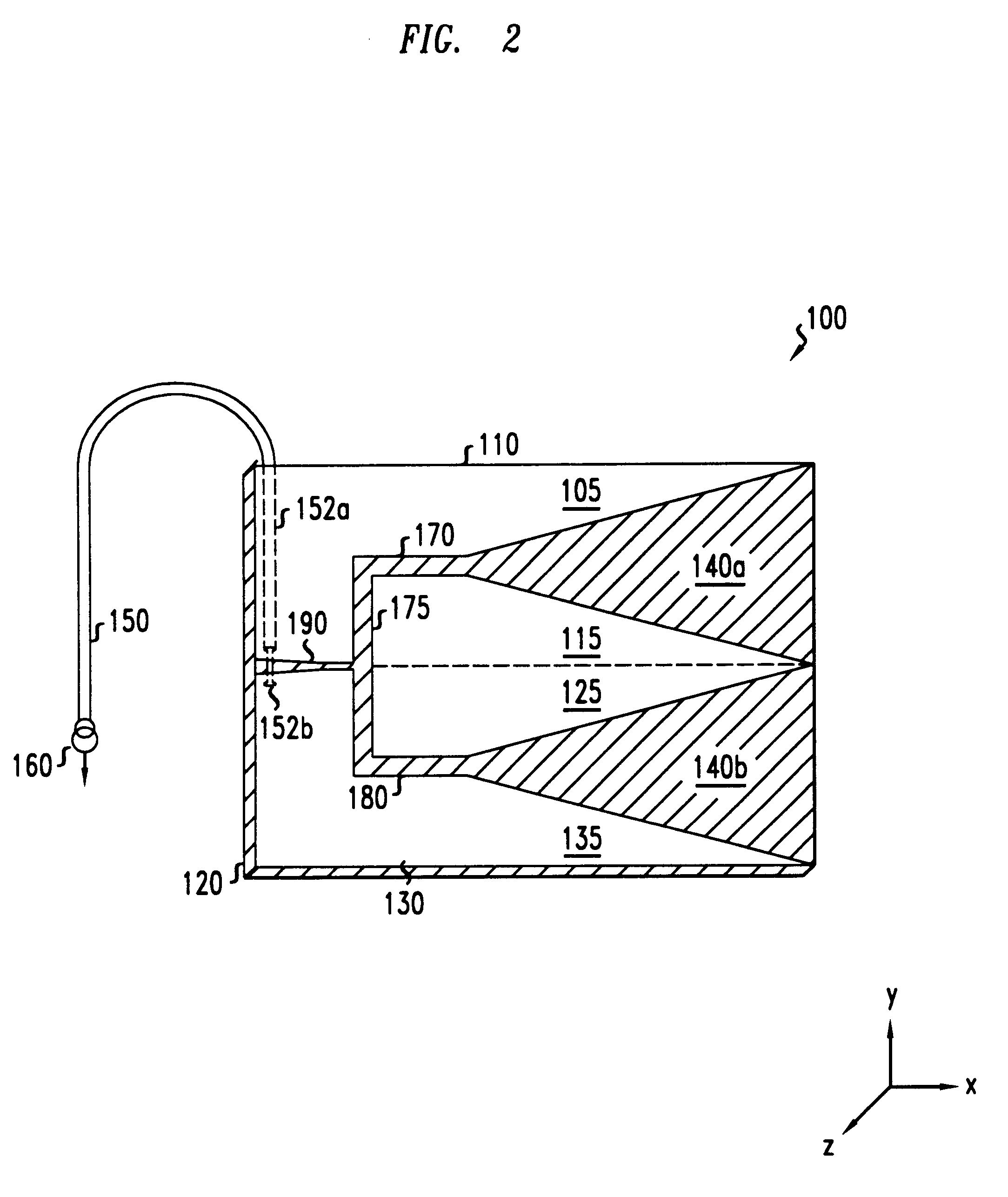
We have invented an antenna structure capable of supporting an increased number of frequency bands. More particularly, we have invented an interface between the balanced impedance and an unbalanced impedance, which does not have the balun's limiting effect on an antenna structure's frequency response. In accordance with the present invention, a slotline couples an antenna structure formed from a balanced transmission line, for example, with an unbalanced transmission line, such as a coaxial cable, for example. We have recognized that the frequency response of an antenna structure may broadened by replacing a balun with a slotted transmission line (e.g., slotline).

Problems solved by technology

The inclusion of a balun, however, has a limiting effect on the frequency response of an antenna structure.
The frequency limitations of baluns in antenna structures has now become a problem.

Method used


Image

  • Broadband antenna structure
  • Broadband antenna structure
  • Broadband antenna structure

Examples


Embodiment Construction

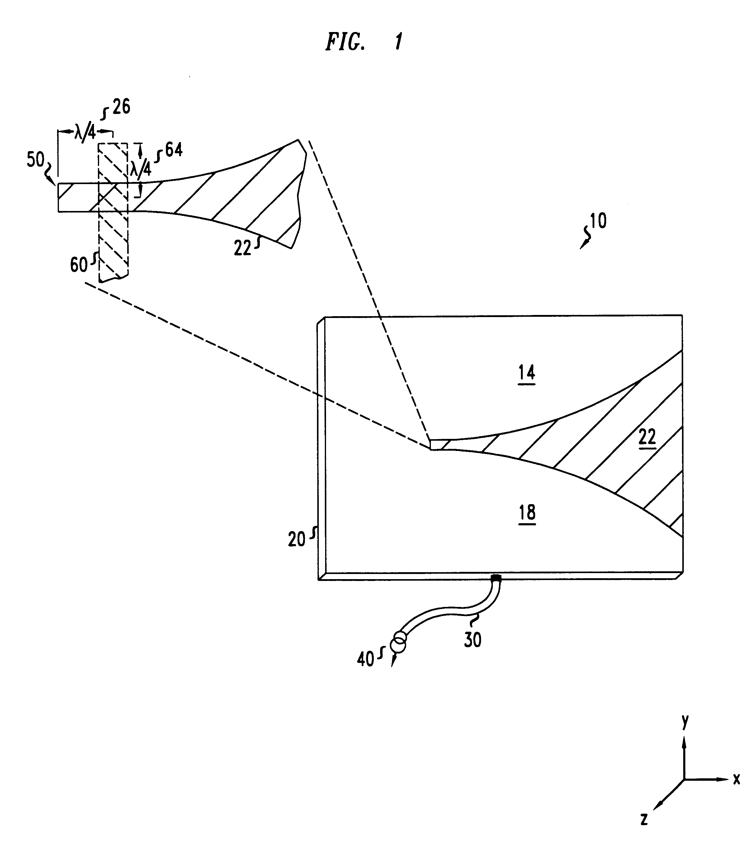
Referring to FIG. 1, a perspective view of a known antenna structure 10 employing a balun is shown. Antenna structure 10 radiates and / or captures electromagnetic energy. Antenna structure 10 has a balanced configuration. More particularly, antenna structure 10 comprises a first and a second conductive film or leaf, 14 and 18, formed on a dielectric substrate 20. First and second conductive leaves, 14 and 18, support the propagation of balanced signals therethrough--i.e., a symmetrical pair of signals which are equal in magnitude and opposite in phase. Separating first and second leaves, 14 and 18, is an expanding non-conductive, tapered slot 22. Tapered slot 22 exposes the dielectric characteristics of substrate 20 such that antenna structure 10, as depicted, has a planar, travelling wave design. As shown, antenna structure 10 may be classified as an endfire-type because it radiates and / or captures electromagnetic energy from its exposed end--i.e., in the direction of the x-axis.

Cou...


PUM


Abstract

An antenna structure including at least one planar antenna element. In place of a balun, the antenna structure further includes a slotline for coupling the planar antenna element with an unbalanced load.

Description

FIELD OF THE INVENTIONThe present invention relates to antennas.BACKGROUND OF THE INVENTIONA balun is an electromagnetic device for interfacing a balanced impedance, such as an antenna, with an unbalanced impedance. A balanced impedance may be characterized by a pair of conductors, in the presence of a ground, which support the propagation of balanced signals therethrough. A balanced signal comprises a pair of symmetrical signals, which are equal in magnitude and opposite in phase. In contrast, an unbalanced impedance may be characterized by a first conductor for supporting the propagation of unbalanced (i.e., asymmetrical) signals therethrough with respect to a second conductor (i.e., ground). A balun converts the balanced signals propagating through the balanced impedance to unbalanced signals for propagating through the unbalanced impedance, and vice versa.Baluns have been employed in various applications. One such application for baluns is in radio frequency ("RF") antenna struc...

Claims


Application Information

Patent Timeline
Patent Type & Authority Patents(United States)
IPC IPC(8): H01Q13/08H01Q9/04H01Q13/22H01Q1/36H01Q1/38H01Q13/00
CPCH01Q9/045H01Q13/085H01Q9/0457H01Q13/00
Inventor FLEMING, DEBRA A.PETERSON, GEORGE EARLTHOMSON, JR., JOHN
Owner LUCENT TECH INC
Why Eureka
Try Eureka