Projector

a projector and projector body technology, applied in the field of projectors, can solve the problems of preventing the miniaturization of the projector, the freedom of the design layout of the internal parts, and the limited arrangement of the projector

Inactive Publication Date: 2003-04-01
SEIKO EPSON CORP
View PDF9 Cites 22 Cited by
  • Summary
  • Abstract
  • Description
  • Claims
  • Application Information

AI Technical Summary

Benefits of technology

In the structure according to the present invention, since the air-inlet is formed on the side of the outer case, the possibility of sucking dust on the set-up place of the projector is reduced, and it is difficult for dust to stick to the periphery of the air-inlet, which enables the projector to be dust-proof without requiring a filter on the air-inlet. Even when a filter is attached thereto, it is difficult for dust to stick to the periphery of the air-inlet, which enables the number of replacements of the filter to be reduced. Under certain circumstances, the replacement of the filter can be eliminated. If so, the replacement structure of the filter is not required.
Since the projection lens is generally cylindrical, even when the sirocco fan is arranged to be adjacent to the peripheral face of the projection lens, a clearance is created between the sirocco fan and the projection lens. When the duct is provided with the recess having a shape corresponding to that of such a clearance so as to be adjacent to and oppose the projection lens, a space in the vicinity of the air-inlet of the sirocco fan can be certainly secured as a space within the duct, so that the cooling air flows into the air-inlet of the sirocco fan smoothly.

Problems solved by technology

An axial-flow fan used as a cooling fan must be arranged close to the internal elements that need to be cooled, resulting in frequent limitations of the arrangement within the projector.
Therefore, the problem arises that the degree of freedom of the design layout of the internal parts, including the fan, is so small that it prevents projector miniaturization.
Thus, the problem also arises of preventing the apparatus height from being reduced and furthermore preventing projector miniaturization.
The air-inlet 2C has individual holes with diameters that are as small as possible, thereby making it difficult for dust on the set-up place of the projector 1 to be sucked into the projector.

Method used


Image

  • Projector
  • Projector
  • Projector

Examples


Embodiment Construction

]

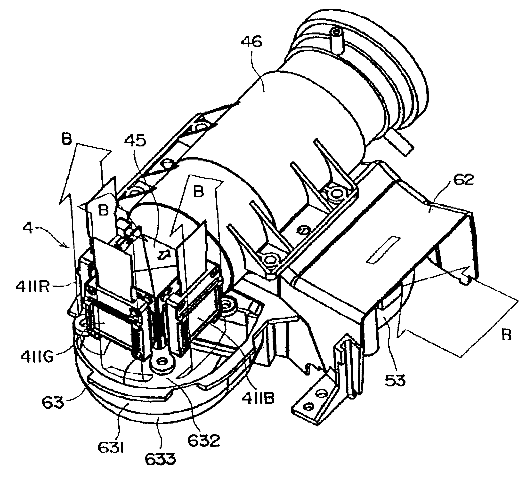
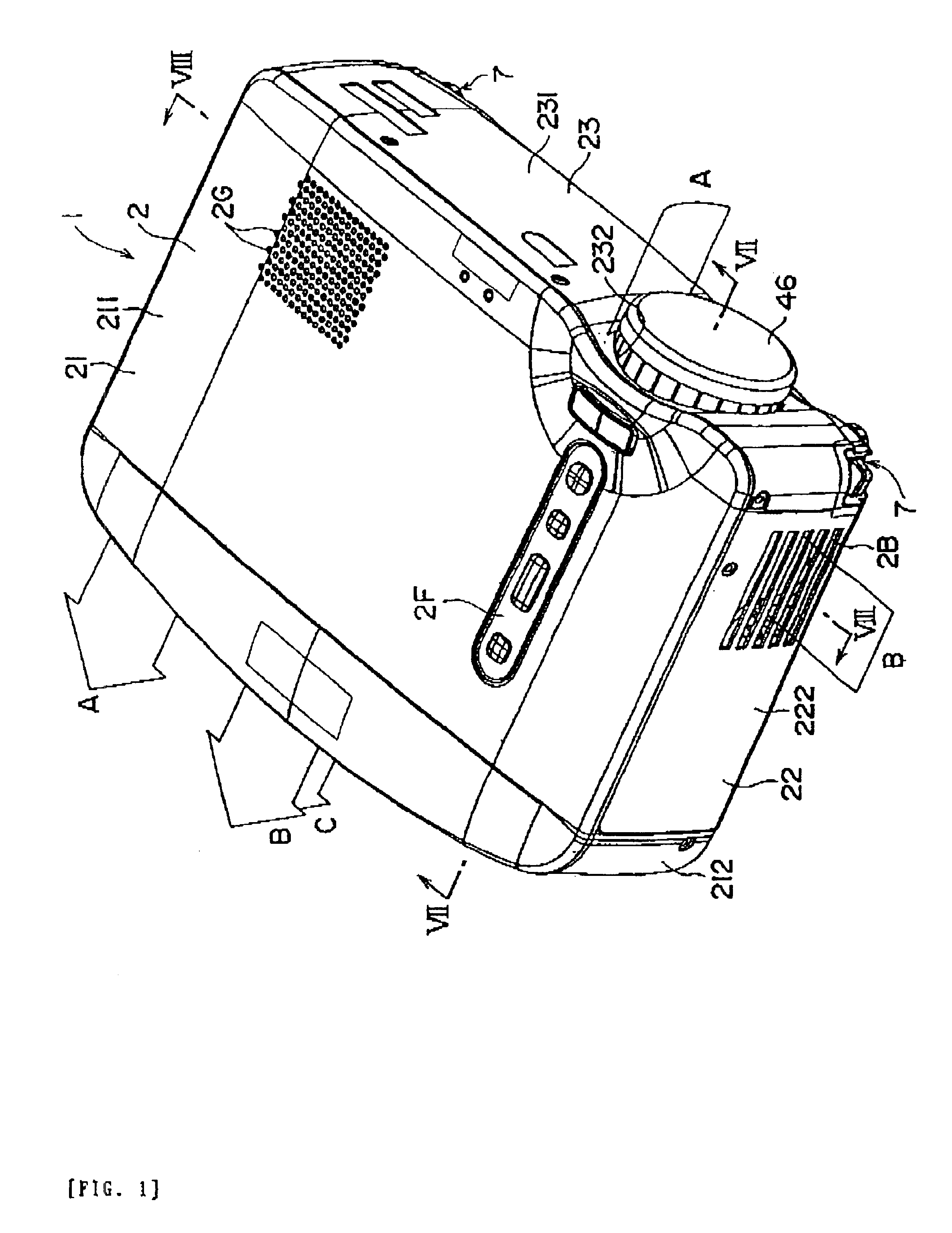
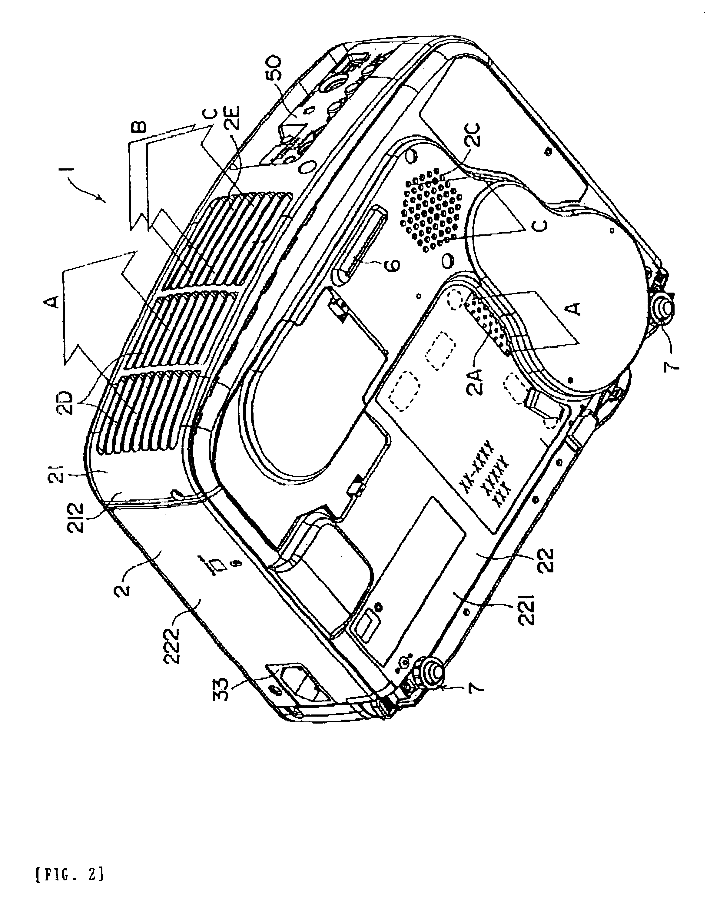
(1) In the second cooling system B according to the embodiment, since the second sirocco fan 53 with the air-inlet 531 opposing the projection lens 46 is used as a receiving fan, and the air-inlet 2B is also formed on the side face 222 of the lower case 22, it is not necessary to provide any air-inlet on the bottom face 221 or the top face 211 of the outer case 2. Therefore, dust on the set-up place of the projector 1 is prevented from being sucked into the projector, and it is difficult for dust to stick to the periphery of the air-inlet 2B, enabling the projector to be dust-proof without any filter on the air-inlet 2B. Even when a filter is attached thereto, it is difficult for dust to stick to the periphery of the air-inlet, enabling the number of replacements of the filter to be reduced. Under certain circumstances, the replacement of the filter can be eliminated. If so, the replacement structure of the filter is not required.

When the filter or the replacement structure of the ...


PUM

PropertyMeasurementUnit
luminous fluxaaaaaaaaaa
shapeaaaaaaaaaa
CTaaaaaaaaaa

Abstract

The invention provides a projector capable of reducing costs and promoting miniaturization while also being dust-proof. A second sirocco fan with an air-inlet opposing a projection lens is used, and an air-inlet of an outer case is formed on a side face thereof. Thereby, it is difficult for dust to be sucked therein compared with an air-inlet formed on the bottom or top face of the outer case, enabling the projector to be dust-proof without any filter. Since the filter is not required, the number of parts is reduced, thereby reducing costs. Furthermore, the second sirocco fan is placed by utilizing a space under the projection lens, which is liable to be a dead space, enabling the arrangement space to be efficiently used thereby promoting miniaturization of a projector.

Description

1. Field of InventionThe present invention relates to a projector for forming a projected image by magnifying and projecting luminous flux emitted from a light source via a projection lens after being modulated.2. Description of Related ArtRecently, the number of environments in which projectors are used has increased, and apart from being used solely for presentations in office meetings or meetings on business trips, projectors are now being used at technical meetings in research and development divisions, etc., for capturing CAD / CAM / CAE data therein in order to magnify and project the data, or at various seminars and learning courses. Projectors are now also being used in school classes where audiovisual education is carried out. The projectors are also used for studying therapeutic methods and for performing medical guidance by projecting medical images and data, such as CT scans and MRI, and they are also used for efficiently addressing attendees at exhibitions or conventions in...

Claims


Application Information

Patent Timeline
Patent Type & Authority Patents(United States)
IPC IPC(8): G03B21/18G03B21/00G03B21/16G02F1/13H04N5/74
CPCG03B21/18
Inventor TAKIZAWA, TAKESHIITO, SHINSUKE
Owner SEIKO EPSON CORP
Why Eureka
Try Eureka