Electronic distance measuring device

a technology of electronic distance measurement and measuring device, which is applied in the direction of distance measurement, instruments, surveying and navigation, etc., can solve the problems of inability to control the exact time of emitted light pulses, short range, and a problem of passive q-switching

Inactive Publication Date: 2003-04-08
SPECTRA PRECISION
View PDF30 Cites 51 Cited by
  • Summary
  • Abstract
  • Description
  • Claims
  • Application Information

AI Technical Summary

Benefits of technology

The light source disclosed in the specification mentioned above generates an emitted beam having a small diameter. By means of a beam expander the beam divergence can be minimised to a suitable level and the beam can be given an adapted beam diameter. For example, it is possible to choose a divergence of 0.3 mrad and to have a beam diameter of less than 5 mm. The microchip laser emits normally light within the infrared (IR) wavelength band. However, a frequency doubling crystal could be provided at the output of the laser or inside the laser cavity in order to generate visible light.
The invention relates to an electronic distance measuring device which measures the propagation time to and from a target of a short pulse of a transmitted electromagnetic beam from a radiation source comprising a microchip laser, and comprising objective optical system for the reflected beam from the target and a detecting unit to which the received beam is transmitted. Means is provided for making the transmitted and the receiving electromagnetic beam coaxial. Means are also provided for focusing the received beam onto the detecting unit. A means makes the transmitted electromagnetic beam simultaneously as narrow and as collimated as possible in order to get a well-defined radiation measuring spot on the target. A control means determines the times of each transmitted electromagnetic pulse by means of a fixed electronic reference.

Problems solved by technology

However, the passive Q-switching gives a problem due to the fact that the exact time for emitting the light pulses can not be controlled.
This system allows, however, the use of a well collimated light beam but the range is too short for most applications.

Method used


Image

  • Electronic distance measuring device
  • Electronic distance measuring device
  • Electronic distance measuring device

Examples


second embodiment

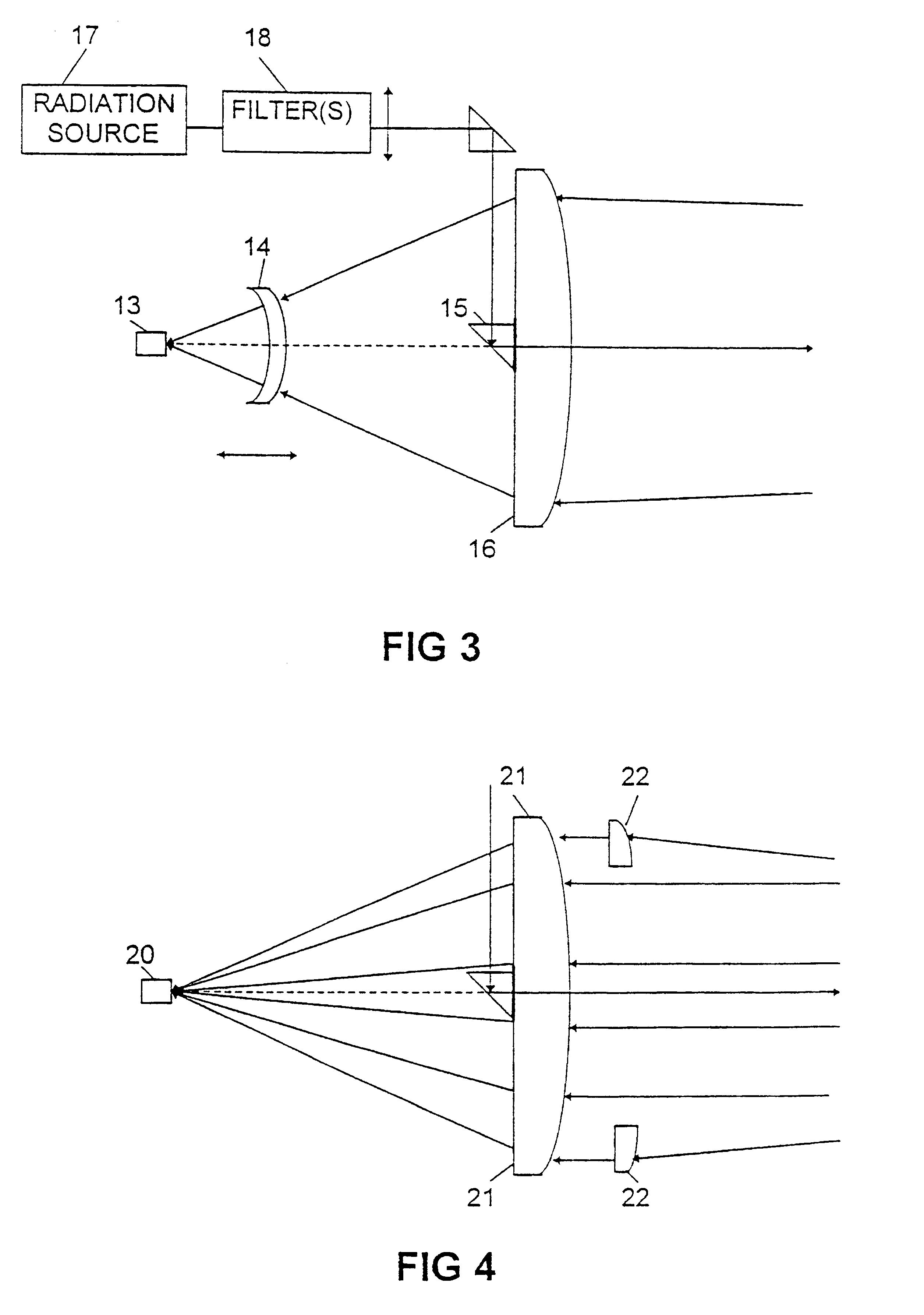
In the second embodiment shown in FIG. 3 the detector unit 13 is immovably fixed, and a lens 14 (or a lens system) is movably positioned, manually or automatically, between the objective lens 16 and the detector unit 13 in order to create an adjustable focal distance. The detector can always be positioned in focus in this way. (It is to be noted that a movable lens instead could be positioned outside the objective lens 16 in the position shown in FIG. 4.) The detector unit 13 could also in this embodiment.comprise a detector element having an optical fibre in front of it as in the embodiment in FIG. 1 (not shown).

In the embodiment shown in FIG. 3 the light source 17 could be a microchip laser emitting IR radiation and having a beam expander (not shown in this embodiment). The light source is in this embodiment provided with a frequency doubling crystal to transform the laser light into visible light. The doubling efficiency is not very high. Both IR radiation and visible radiation w...

third embodiment

In the third embodiment, shown in FIG. 4, which only shows the optical elements, the detector unit 20 is also fixedly mounted in relation to the objective lens 21. An optical element 22 is designed such that the part of the beam passing through it and the lens 21 is deviated with a different focal length than the part that passes only through the lens 21. The focal length of the double system 21, 22 is adapted to nearby objects. By suitable optimisation of the focal lengths and dimension of the element 22, and by using the aberrations in the optical system it is possible to obtain a high enough signal at the detector / detector fibre within a chosen object distance interval. It is to be noted that instead of having the extra optical element outside the objective lens 21 it could be seated inside this lens for example in the position shown for the lens 14 in FIG. 3.

The optical element 22 is preferably ring shaped, but in principle other shapes are possible, like for example a segment o...


PUM


Abstract

The invention relates to an electronic distance measuring device which measures the propagation time to and from a target of a shor pulse of a trasmitted electromagnetic beam from a radiation source comprising a microchip laser, and comprising objective optical system (6; 16; 21); for the reflected beam from the target and a detecting unit (9; 13; 20) to which the received beam is transmitted. Means (4, 5; 15) is provided for making the transmitted and the receiving electromagnetic beam coaxial. Means (6, 10, 12; 14, 16; 21, 22) are also provided for focusing the received beam onto the detecting unit (9; 13; 20). A means (3) makes the transmitted electromagnetic beam simultaneously as narrow and as collimated as possible in order to get a well-defined radiation measuring spot on the target.

Description

This invention relates to an electronic distance measuring device of the kind in accordance with the preamble of claim 1.Electronic distance meters (EDM) which measure by directing an electromagnetic beam, such as a light beam, towards a target and collecting reflected radiation are principally of the phase measuring or the propagation delay time measuring kind. Some of these kinds of measuring instruments are adapted for making distance measurements against natural objects, i.e. against objects which are not provided with reflectors, for example prism reflectors, such as cube corner reflectors. A phase measuring distance meter uses a more or less continuous emitted beam, i.e. a beam provided with an almost symmetric modulation with one or more frequencies, but there are also phase measuring instruments working with short pulses. A propagation time measuring distance meter uses short pulses, which are emitted repeatedly with a determined pulse emission rate where the time interval b...

Claims


Application Information

Patent Timeline
Patent Type & Authority Patents(United States)
IPC IPC(8): G01C3/08G01S17/10G01S17/00G01S7/48G01S7/497G01S7/481G01C3/06G01S17/08G01S17/14
CPCG01C3/08G01S7/4812G01S7/497G01S17/10G01S17/105G01S7/4818G01S17/14
Inventor ANDERSSON, LEIF
Owner SPECTRA PRECISION
Why Eureka
Try Eureka