
Radio frequency transmission control apparatus for preventing oscillation in wideband wireless local loop terminal

a control apparatus and radio frequency technology, applied in the direction of antennas, network topologies, electrically long antennas, etc., can solve the problems of power loss, reduced radio port capacity, overload problem,

Inactive Publication Date: 2003-04-15
PANTECH CORP
View PDF4 Cites 17 Cited by
  • Summary
  • Abstract
  • Description
  • Claims
  • Application Information

AI Technical Summary

Problems solved by technology

When each active element of the radio frequency transmitting unit 40 is thus-provided with a power through the line (TX_VCC), an overload problem may occur.
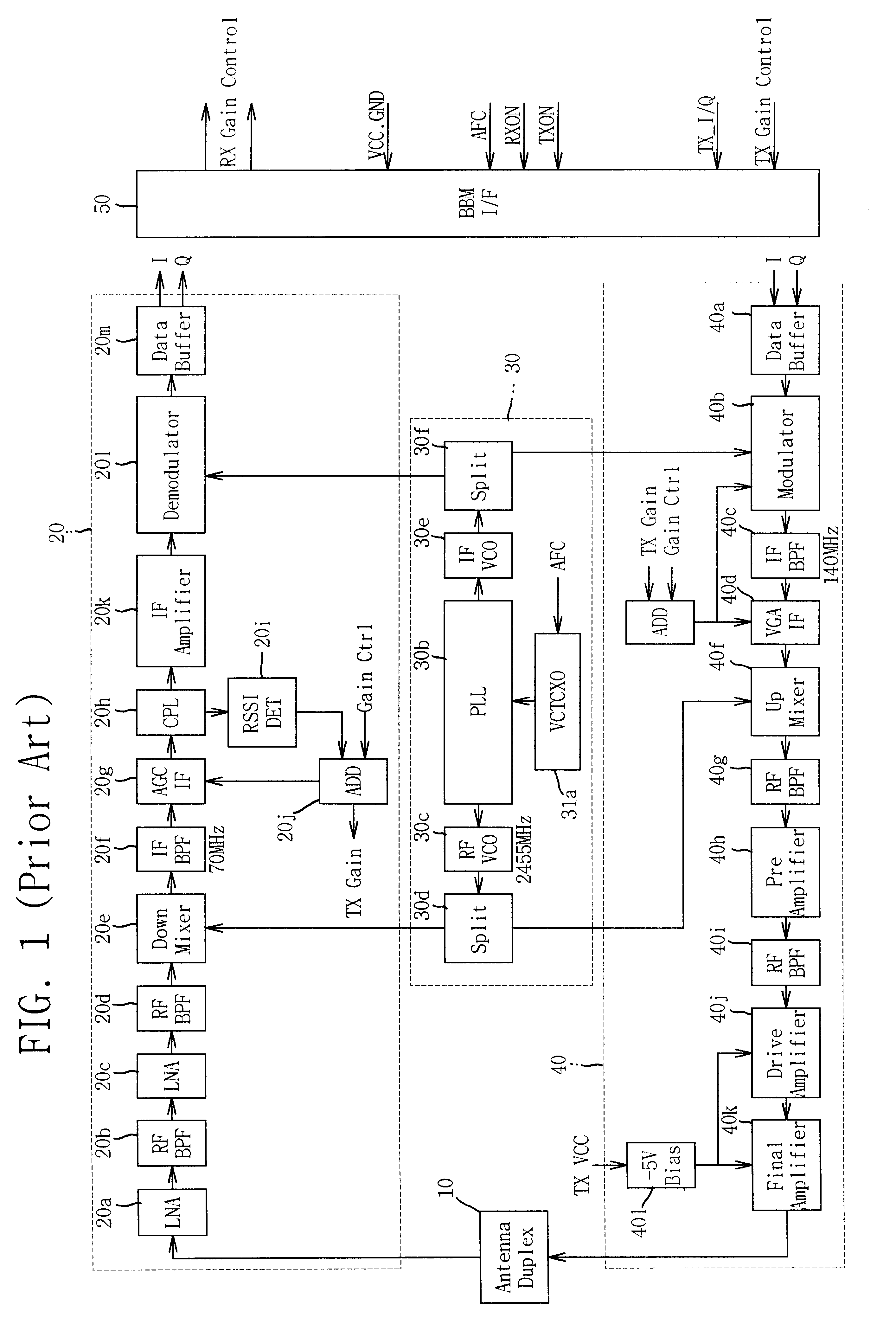
Further, an additional problem may occur in that the radio frequency transmitting unit 40 outputs an undesired oscillation frequency while I-signal (TX_I) and Q-signal (TX_Q) output from the BBM interface unit 50 are transmitted to the power amplifier 40k, i.e., the final amplifier, via the data buffer 40a.
In addition, such an oscillation may reduce capacity of the radio port when a wireless communication is performed.
During the delay time period until the transmitting signals are sequentially input from the data buffer 40a, that is, during the time period where the operation of the power amplifier 40k is not required, the power amplifier 40k which ranks highest power consumption among active components of the radio frequency transmitting unit 40 operates, which may result in a power loss.
Thus, other active elements except the power amplifier 40k may consume unnecessary power.

Method used


Image

  • Radio frequency transmission control apparatus for preventing oscillation in wideband wireless local loop terminal
  • Radio frequency transmission control apparatus for preventing oscillation in wideband wireless local loop terminal
  • Radio frequency transmission control apparatus for preventing oscillation in wideband wireless local loop terminal

Examples


Embodiment Construction

The present invention will be explained in more detail with reference to the attached drawings.

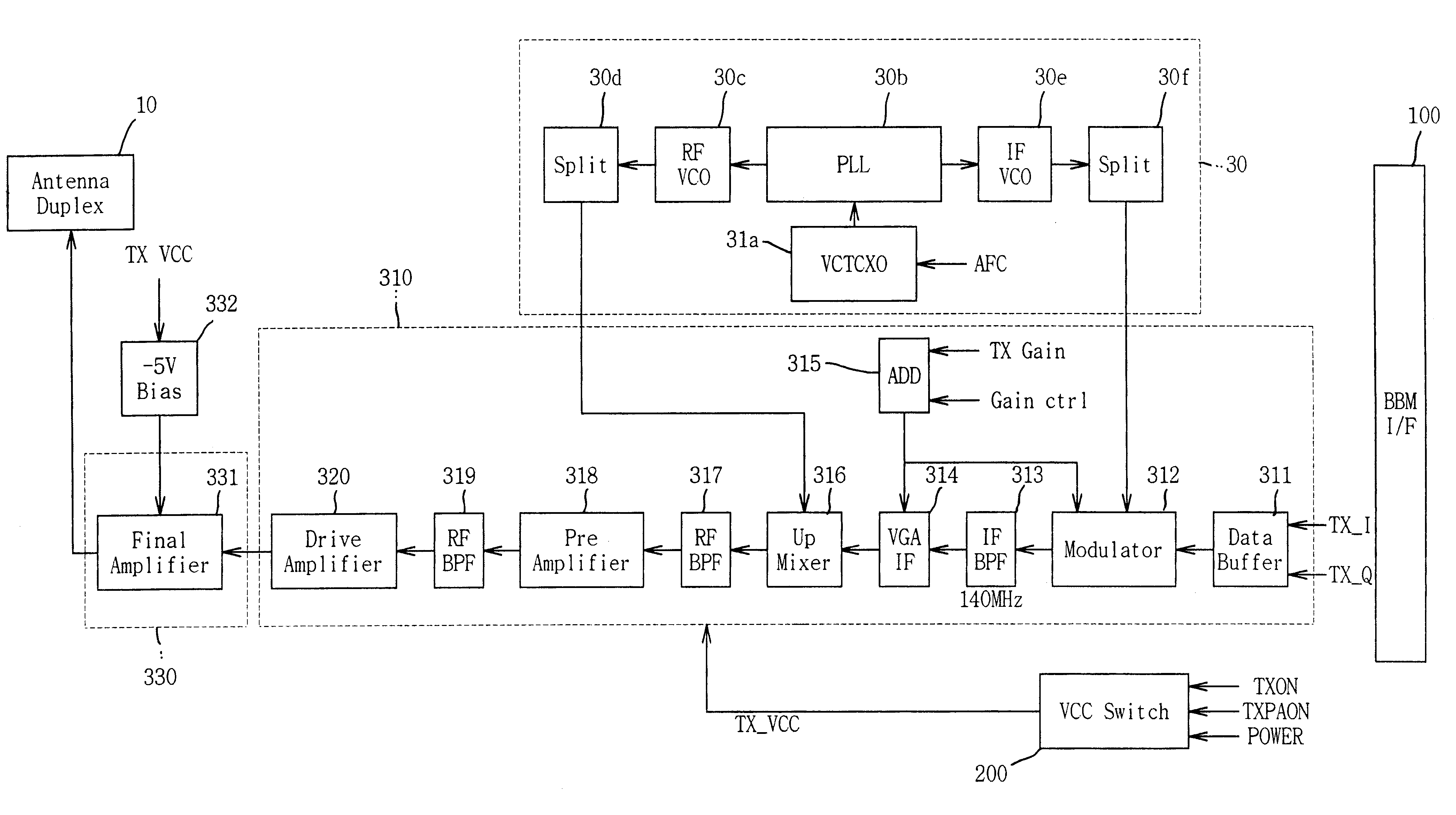
Referring to FIG. 4, a BBM interface 100 is matched to the BBM for processing a digital signal of W-WLL terminal, and transmits I-signal (TX_I), Q-signal (TX_Q) and a signal for power supply control to the radio frequency transmitting unit which is divided into a radio frequency converting unit 310 and a power amplifier unit 330.

The local clock generating unit 30 has a configuration same as that of the local clock generating unit included in a conventional radio frequency transmitting unit or radio frequency receiving unit. That is, the local clock generating unit 30 includes a reference clock generating unit (VCTCXO) 30a for generating a reference clock having a voltage / thermal sensitivity according to a control of the BBM connected to the BBM interface 100; an RF VCO(voltage controlled oscillator) 30c for generating a local RF using an output signal of the VCTCXO 30a; an IF VCO 30e for g...


PUM


Abstract

A radio frequency transmission control apparatus for preventing an oscillation in a wideband wireless local loop terminal has a radio frequency transmitting unit for modulating a baseband transmitting signal to a WLL radio frequency band signal and transmitting the modulated signal via an antenna, and the radio frequency transmitting unit is divided into a radio frequency converting unit and a power amplifier unit in accordance with characteristics of each active element constituting the radio frequency transmitting unit. When a power is supplied to the radio frequency transmitting unit, the power is first supplied to the radio frequency converting unit so as to maintain the same at an operating state. After a predetermined time period has elapsed, the power is supplied to the power amplifier unit. When the radio frequency transmitting unit is cut off from a power, a cutoff of the power amplifier unit is performed prior to a cutoff of the radio frequency converting unit, to thereby prevent generation of an oscillation frequency in W-WLL terminal.

Description

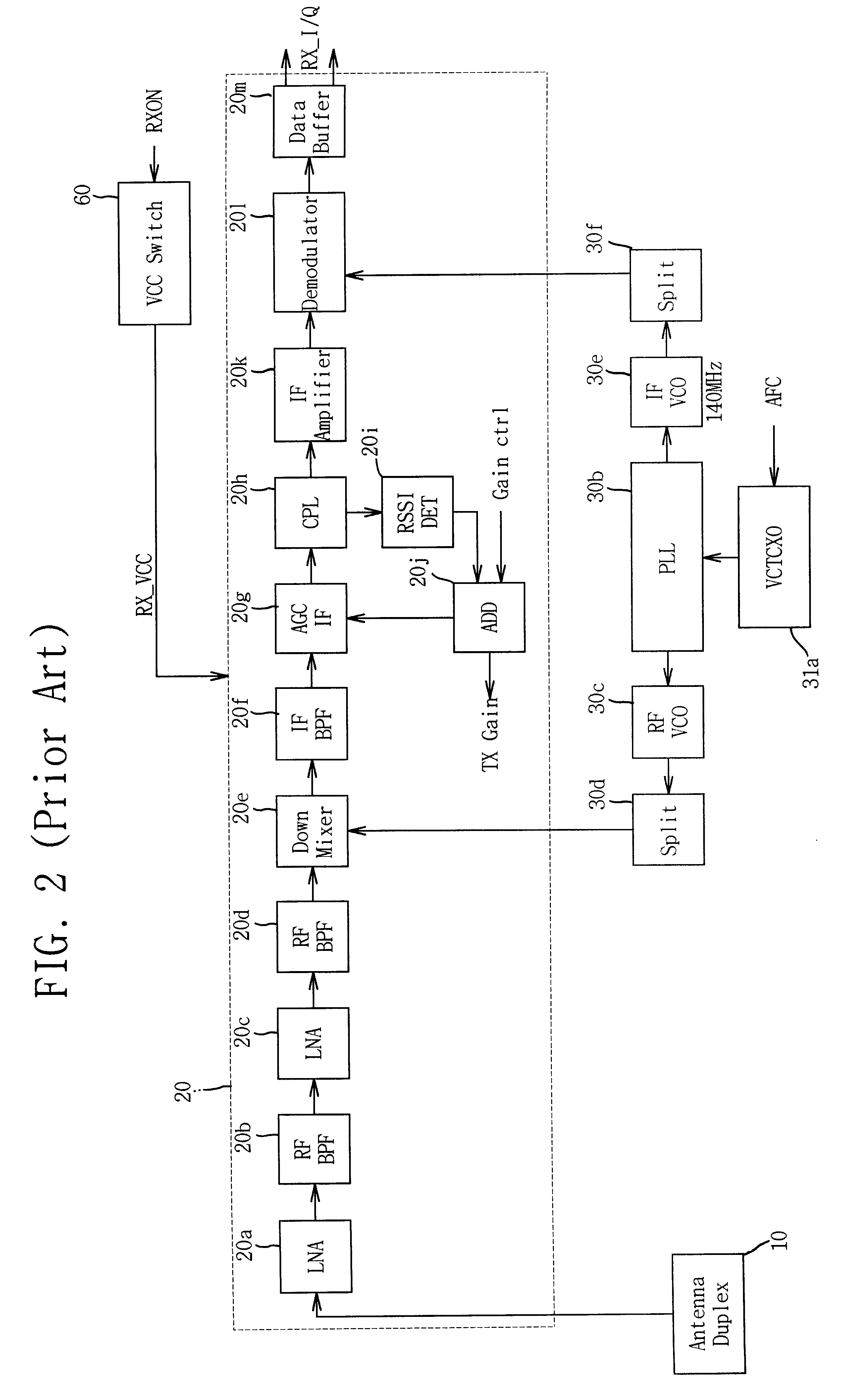
1. Field of the InventionThe present invention relates to a radio frequency processing apparatus of a wideband wireless local loop (W-WLL), and more particularly, to a radio frequency transmission control apparatus for preventing oscillation in a W-WLL terminal, in which power supply is controlled in accordance with characteristics of each active element of radio frequency transmitter unit in the W-WLL terminal, to thereby eliminate an oscillation caused by a simultaneous power supply to the radio frequency processing apparatus and minimize power consumption.2. Description of the Related ArtFIG. 1 is a block diagram illustrating a radio frequency processing apparatus of a common W-WLL terminal.Referring to FIG. 1, the radio frequency processing apparatus includes a radio frequency receiving unit 20 for demodulating an WLL radio frequency band signal received via an antenna to a baseband signal so as to be processed in a modem; a radio frequency transmitting unit 40 for modulating th...

Claims


Application Information

Patent Timeline
IPC IPC(8): H04B1/04H04B7/24
CPCH04B1/0475H04W88/02H04W84/14
Inventor KIM, CHEUL-HONG
Owner PANTECH CORP
Learn More