
Temperature control method and system for thermal fixing unit, and image forming apparatus

a technology of thermal fixing and temperature control method, which is applied in the direction of electrographic process apparatus, ohmic-resistance heating, instruments, etc., can solve the problems of excessive fixing condition and paper sheet wrinkles, and achieve the effect of improving print quality, convenient access, and maintaining print quality

Inactive Publication Date: 2003-04-22
FUJIFILM BUSINESS INNOVATION CORP
View PDF14 Cites 65 Cited by
  • Summary
  • Abstract
  • Description
  • Claims
  • Application Information

AI Technical Summary

Benefits of technology

That is, as mentioned above, when the interval between the record mediums 1 exceeds a predetermined value, the controlled target temperature for the thermal fixing unit 10 is switched to be lower than a preset controlled target temperature for the consecutive image formation, with the result that it is possible to suppress the occurrence of excessive fixing resulting from the excessive heating of the pressure roller 13 by the heating roller 11. Accordingly, the balance between fixing rate and the occurrence of wrinkles is maintainable irrespective of the large variation of the distance between paper sheets within the printer.
Besides, since the detection of the arrival time interval of image formation data is made for the detection of the interval between the record mediums 1 the record medium 1 is easily obtainable without relying upon the actual measurement.
Particularly, although, with the recent progress of OA, there is a greater tendency for the print data evolution time to greatly vary because various types of data exist in a mixed condition on one page, as mentioned before, this invention can surely prevent the occurrence of wrinkles on paper sheets after fixing and remarkably improve the print quality even if the print data evolution time greatly varies, that is, the distance between the paper sheets largely varies within the printer.

Problems solved by technology

Conversely, if the temperature of the heating roller 192 is not set to a relatively low value, an excessive fixing condition is liable to occur to produce wrinkles on paper sheets.

Method used


Image

  • Temperature control method and system for thermal fixing unit, and image forming apparatus
  • Temperature control method and system for thermal fixing unit, and image forming apparatus
  • Temperature control method and system for thermal fixing unit, and image forming apparatus

Examples


Embodiment Construction

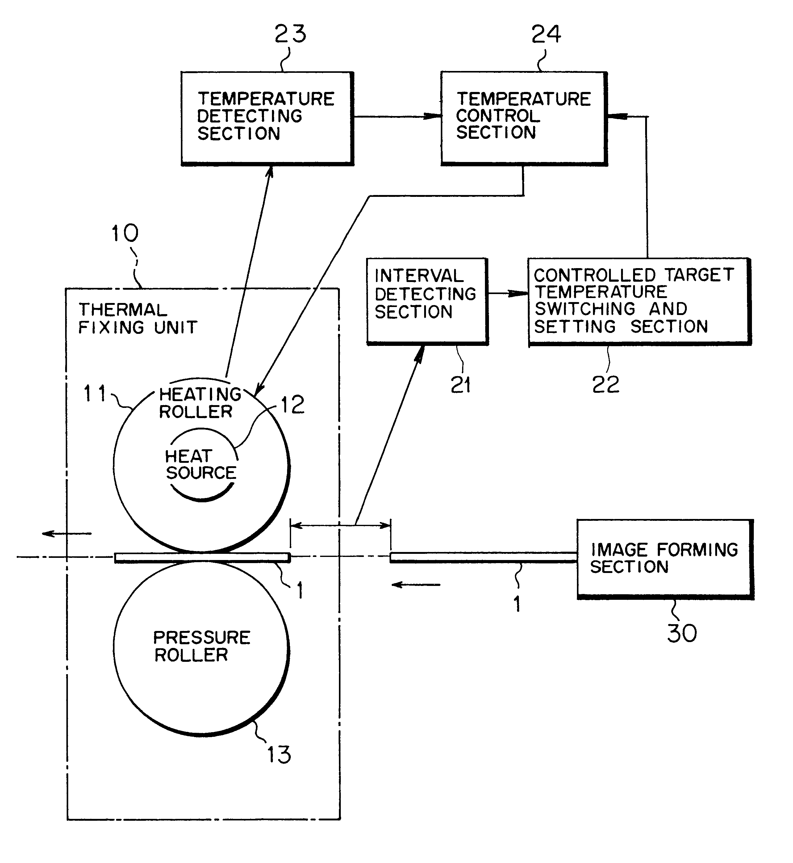
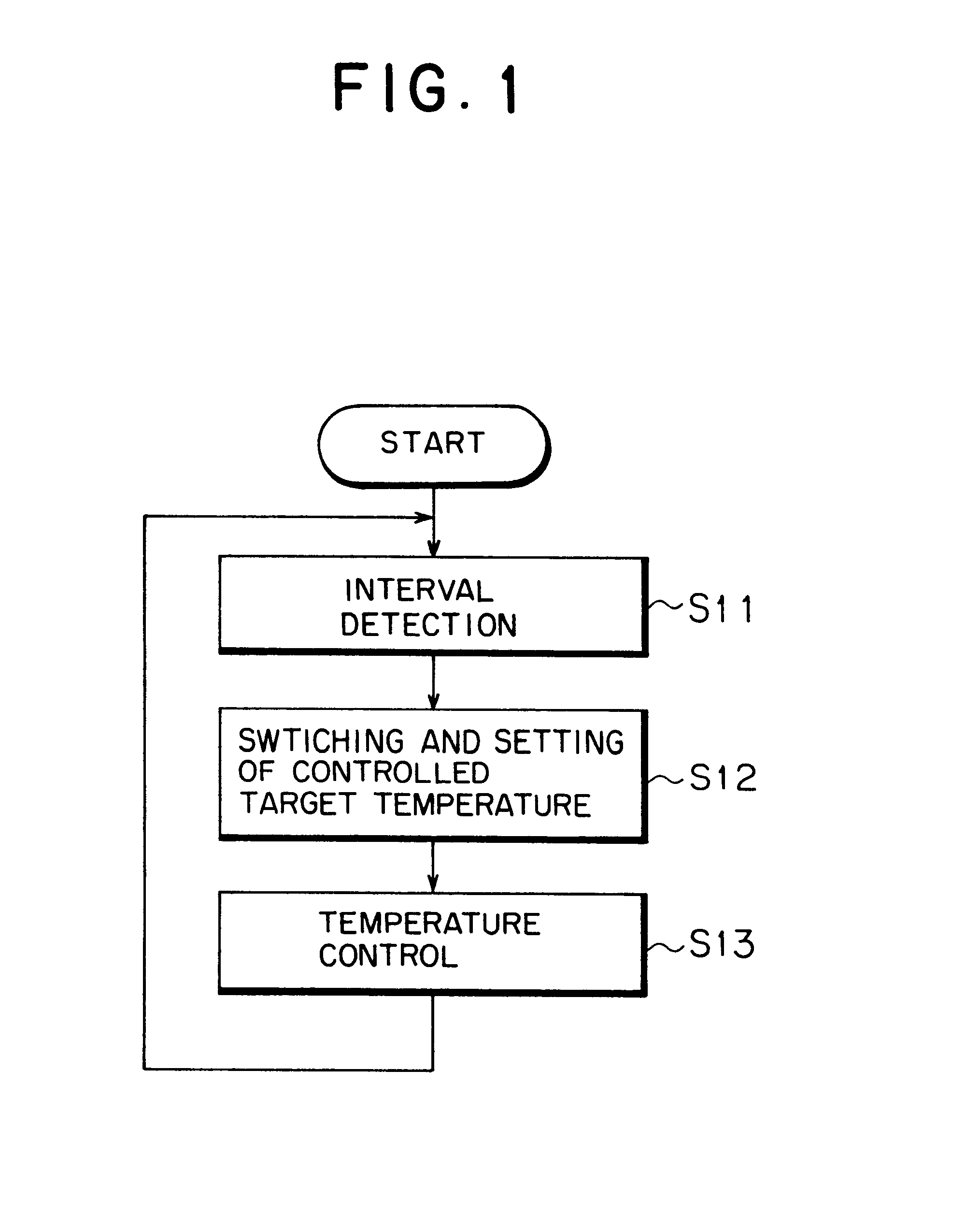
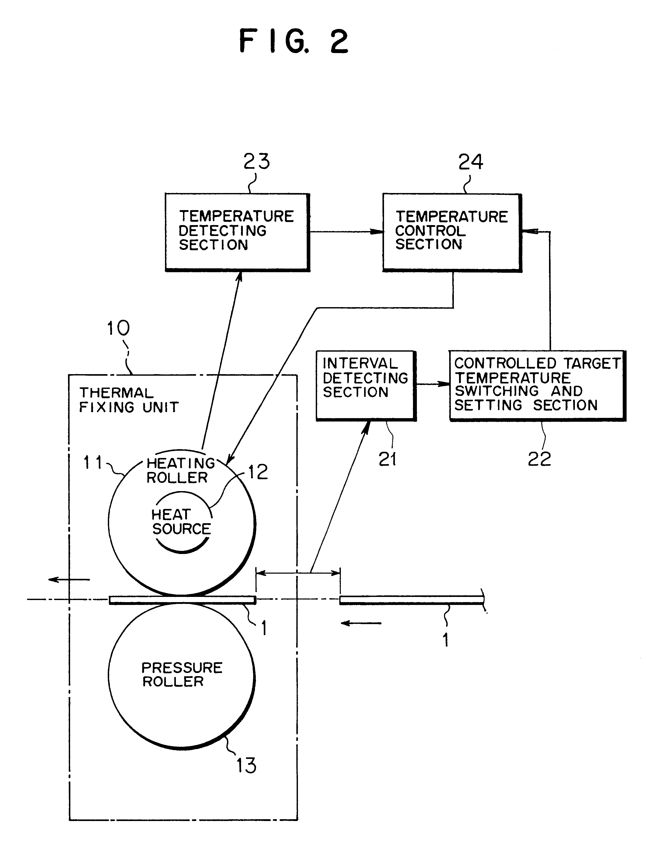
Embodiments of the present invention will be described hereinbelow with reference to the drawings.

FIG. 4 is a perspective view showing an appearance of an electrophotographic printer (laser printer; image forming apparatus) 100 according to an embodiment of this invention, which is, as shown in FIG. 4, made up of a printer body 101 for taking charge of image formation and a paper feeding unit (a double-face printing unit 102 and a first paper feeding unit 103) for feeding paper sheets (record mediums; see reference numeral 1 in FIGS. 2 and 3) to the printer body 101.

The printer body 101 internally contains various units for image formation and medium conveying system which will be described herein later with reference to FIG. 5, and further, is, thereabove, provided with a stacker 111 for receiving and holding paper sheets discharged after printing and an operator control panel 101a the user operates. The operator control panel 101a has buttons to be used for conducting various sett...


PUM


Abstract

Method and apparatus for controlling a temperature of a thermal fixing unit which is for the purpose of maintaining the balance between a fixing rate and the occurrence of wrinkles even if a distance between paper sheets greatly varies within a printer. When image formation is consecutively made onto a plurality of record mediums without stopping an operation of an image forming apparatus, an interval between the record mediums is detected, and a controlled target temperature for a thermal fixing unit is switched and set in accordance with the interval between the record mediums to control a heat source so that the temperature of the thermal fixing unit reaches the controlled target temperature. The image Corming apparatus may include an electrophotographic recording apparatus such as a copying machine, facsimile and laser printer using a toner.

Description

1) Field of the InventionThe present invention relates to a thermal fixing unit which is for use in an image forming apparatus including an electrophotographic recording apparatus such as a copying machine, facsimile and laser printer using a toner, and which thermally fixes an image transferred onto a record medium, and more particularly, relates to a method and system for controlling a temperature of the thermal fixing unit, and further to an image forming apparatus based upon that temperature control technique for the thermal fixing unit.2) Description of the Related ArtIn general, in an image forming apparatus (which will be referred hereinafter to as a printer) including an electrophotographic recording appartus such as a copying machine, a facsimile and a laser printer using a toner, a thermal fixing unit, which thermally fixes a toner image transferred onto a record medium (paper), is located along a record medium conveyance path on the downstream side of a transferring syste...

Claims


Application Information

Patent Timeline
IPC IPC(8): G03G15/20G03G21/14G03G15/00G05D23/19
CPCG03G15/2039
Inventor HIROSE, KAZUNORIMATSUYA, TAKASHI
Owner FUJIFILM BUSINESS INNOVATION CORP
Learn More