Self-inflatable air cushion for shoes

an air cushion and self-inflating technology, which is applied in the direction of fluid mattresses, beds, insoles, etc., can solve the problems of inability to regulate, and the conventional cushion of this type is incapable of providing stable support for the foot of the user

Inactive Publication Date: 2003-04-29
HUANG ING CHUNG
View PDF11 Cites 76 Cited by
  • Summary
  • Abstract
  • Description
  • Claims
  • Application Information

AI Technical Summary

Benefits of technology

It is an object of the present invention to provide a self-inflatable air cushion which comprises a pump in the form of a collapsible plenum chamber having an air hole, a support chamber surrounding the pump, an air passage providing communication between the support chamber and the pump, and an one-way valve disposed in the air passage for permitting air to pass from the pump to the support chamber. When the pump is compressed by the foot of the user, air is forced out of the pump through the one-way valve and into the support chamber. When the foot is released, outside air is drawn into the pump through the air hole. In this way, the firmness of the support chamber may be adjusted. The support chamber is formed from an appropriate material, such as a polymer plastic, which permits it to maintain a preformed three-dimensional structure having sufficient rigidity to provide support for the foot of the user before it has received compressed air from the pump.
A still further object of the present invention includes providing a pressure accumulation chamber which has one end connected to the pump through an one-way valve for permitting air to flow from the pump to the pressure accumulation chamber, and an opposite end connected to the support chamber through an one-way valve for permitting air to flow from the pressure accumulation chamber to the support chamber. When the pump is compressed, compressed air is driven from the pump chamber into the pressure accumulation chamber. Since the support chamber is simultaneously subjected to an external pressure, the compressed air pressure of the pressure accumulation chamber is prevented from passing to the support chamber. When the external pressure is released from the support chamber, the compressed air of the pressure accumulation chamber is permitted to pass to the interior of the support chamber.

Problems solved by technology

If the inside pressure of the air cushion is excessively high, it cannot be regulated.
However, this known construction has a distinct disadvantage in that the chamber surrounding the pump is a of a two-dimensional configuration until it has been inflated by the pump.
Conventional cushions of this type are incapable of providing stable support for the foot of the user until the cushion has been sufficiently inflated with air.

Method used


Image

  • Self-inflatable air cushion for shoes
  • Self-inflatable air cushion for shoes
  • Self-inflatable air cushion for shoes

Examples


Embodiment Construction

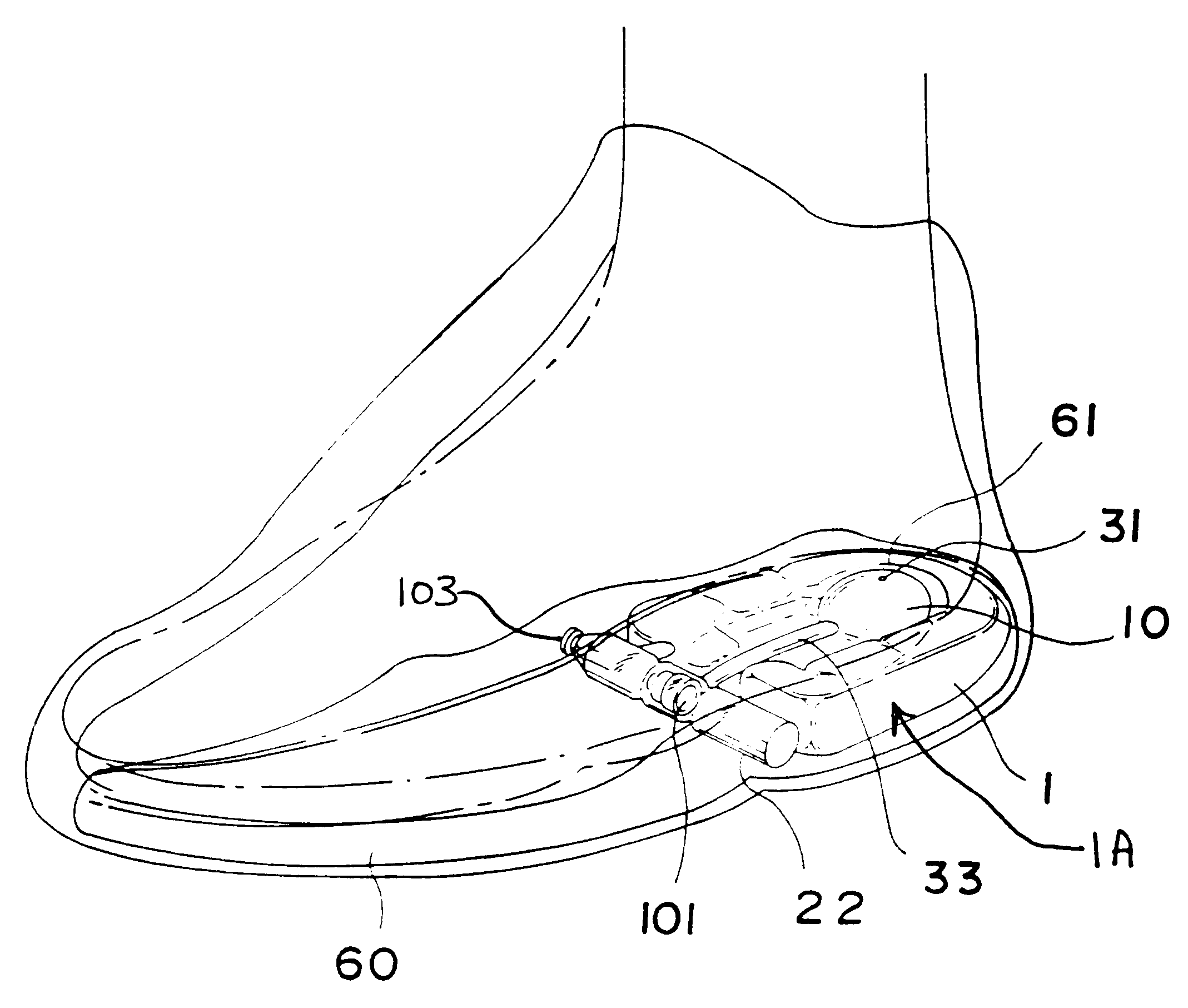
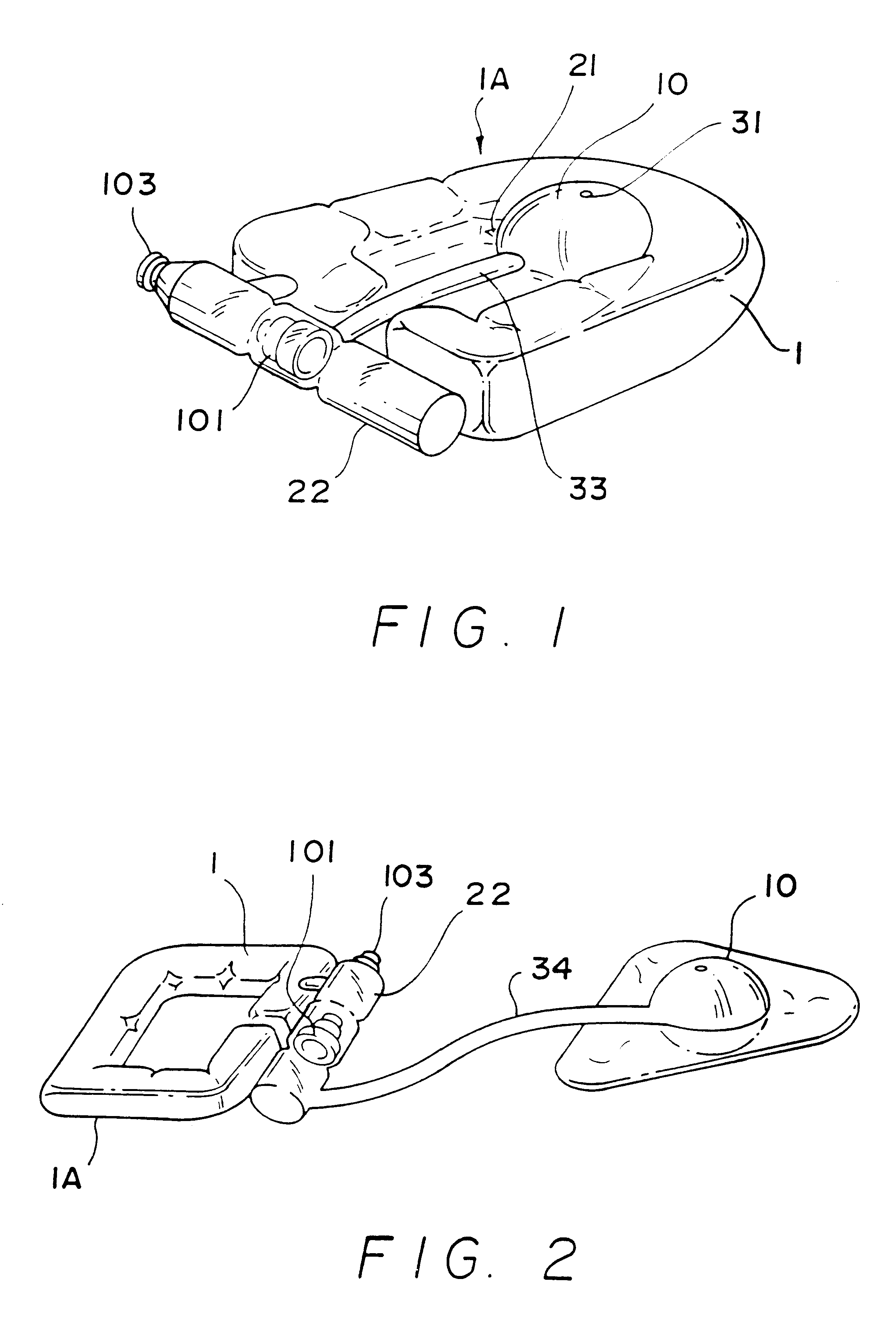
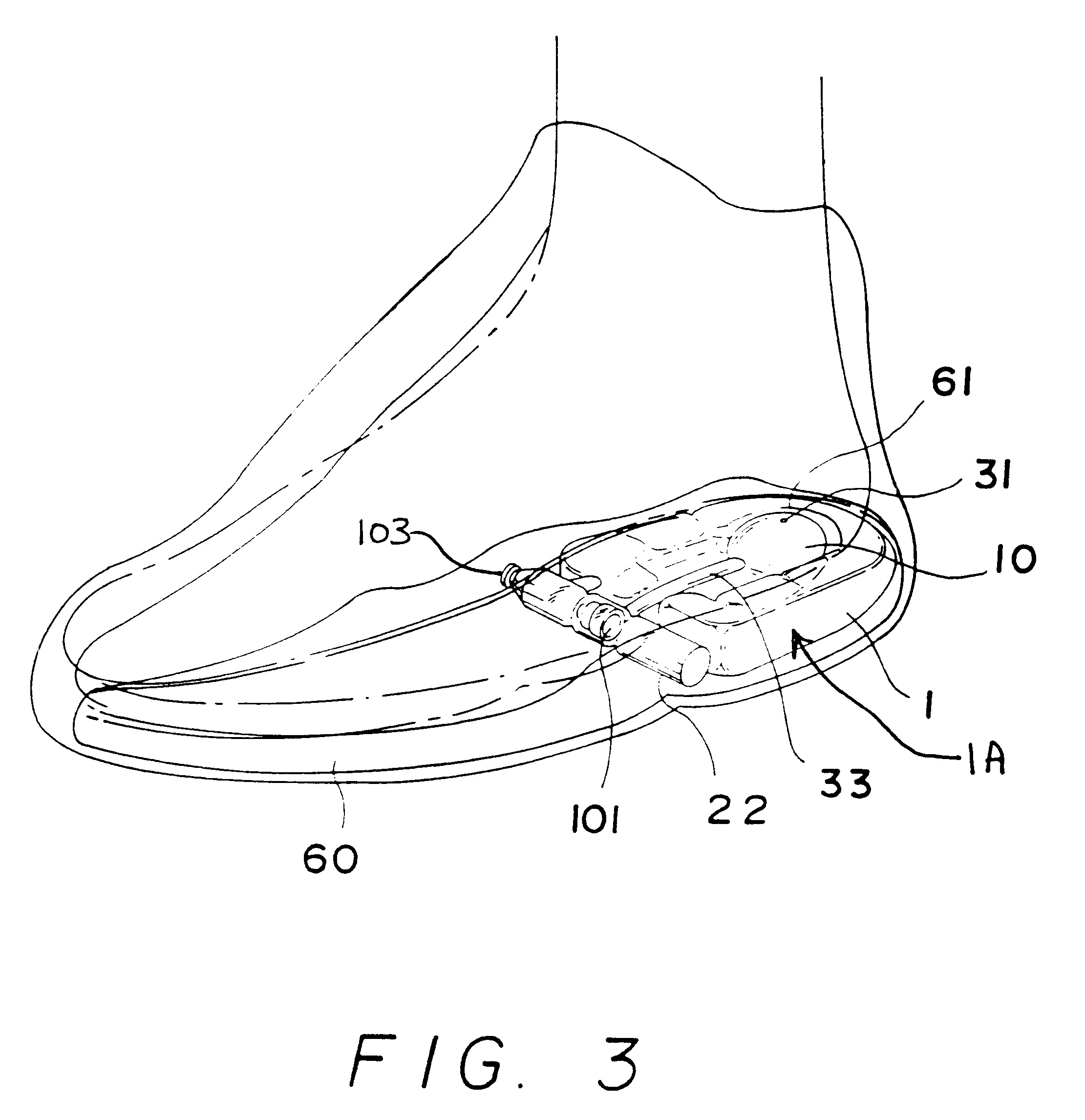
Referring to FIG. 1, a self-inflatable air cushion 1A is shown comprising a support chamber 1, an open space 21 surrounded by support chamber 1, a plenum chamber in the form of a pump 10 disposed in open space 21 and provided with an air hole 31 at a top side thereof, an air cylinder 22 having a rear end disposed in communication with the support chamber 1, a tube 33 forming a passage connecting the pump 10 and air cylinder 22, an one-way valve 101 mounted in the air cylinder 22 for permitting air to pass from the pump 10 through the air cylinder 22 to the interior of the support chamber 1, and a relief valve 103 mounted in a front end of air cylinder 22 for releasing compressed air to the atmosphere.

Support chamber 1 and pump 10 collectively form a cushion system having a central portion defined by pump 10 and an outside portion defined by support chamber 1. Pump 10 functions as an air pump which is actuated by the foot of the user and receives airthrough air hole 31, the air being...


PUM


Abstract

Support is provided to the foot of a shoe wearer by an air cushion that includes a support chamber surrounding a collapsible pump operable by the foot of the wearer for directing compressed air into the support chamber and varying the firmness of the chamber. The support chamber is of a preformed three-dimensional configuration of sufficient rigidity to provide stable support to the foot prior to receiving compressed air from the pump.

Description

BACKGROUND OF THE INVENTIONThe present invention relates to a self-inflatable air cushion for use in shoes, and more particularly to such an air cushion which includes a pump in the form of a collapsible plenum chamber, a support chamber surrounding the pump, and a valve connected between the pump and the support chamber for permitting air to be driven from the pump into the support chamber by compressing the pump with the foot of the user.A conventional air cushion of this type is generally comprised of a collapsible three-dimensional body defining a plurality of air cells and a plurality of passages connecting the air cells. An air valve is also connected to the passages and disposed outside the sole of the shoe. When the air cushion is to be inflated, an air pump is attached to the air valve and operated to pump air into the air cells. If the inside pressure of the air cushion is excessively high, it cannot be regulated. Moreover, known cushions of this type may also include a pu...

Claims


Application Information

Patent Timeline
Patent Type & Authority Patents(United States)
IPC IPC(8): A43B17/03A43B17/08A43B21/00A43B17/00A43B21/28
CPCA43B17/035A43B21/285A43B17/08
Inventor HUANG, ING-CHUNG
Owner HUANG ING CHUNG
Why Eureka
Try Eureka