Coordinated valve timing and throttle control for controlling intake air

a technology of throttle control and valve timing, which is applied in the direction of electrical control, non-mechanical valves, instruments, etc., can solve the problems of inability to control the air charge of the cylinder, the inability to adjust the valve closure timing in certain operations, and the reduction of ride comfort and noise. a considerable amount, and the inability to control the cylinder air charge satisfactorily by unthrottling the intake air control

Inactive Publication Date: 2003-04-29
NISSAN MOTOR CO LTD
View PDF24 Cites 28 Cited by
  • Summary
  • Abstract
  • Description
  • Claims
  • Application Information

AI Technical Summary

Benefits of technology

Because of the provision of intake manifold and collector downstream of a throttle valve, there is a delay, during throttled intake air control, between a change in angular position of the throttle valve and a change in cylinder air charge. In the case of unthrottled intake air control, there is no delay caused due to the intake manifold and collector so that a change in valve closure timing induces a change in cylinder air charge without any delay, providing aggressive response performance. For example, operator aggressive repetition of a cycle of depression and release of accelerator pedal induces such violent variation of torque imparted to a power train induces as to cause vibration, providing a reduction in ride comfort and a considerably high level of noise.
Thus, a need remains to improve an unthrottled intake air control by variable valve timing such that the occurrence of violent torque variation caused by aggressive cyclic depression and release manipulation of an accelerator pedal is prevented and the undesired torque change during transient period from one to the other of the two intake air control mode is suppressed.
It is an object of the present invention to provide a system and method for controlling intake air to an internal combustion engine such that the occurrence of violent torque variation caused by aggressive cyclic depression and release manipulation of an accelerator pedal is prevented and the undesired torque change during transient period from one to the other of the two intake air controls is suppressed.

Problems solved by technology

Due to the limitation of speed at which an EMD can move its intake valve, adjustment of valve closure timing becomes ineffective in intake air control in certain operation range.
Because of the provision of intake manifold and collector downstream of a throttle valve, there is a delay, during throttled intake air control, between a change in angular position of the throttle valve and a change in cylinder air charge.
For example, operator aggressive repetition of a cycle of depression and release of accelerator pedal induces such violent variation of torque imparted to a power train induces as to cause vibration, providing a reduction in ride comfort and a considerably high level of noise.
As mentioned above, unthrottling intake air control cannot control cylinder air charge satisfactorily in certain operation range.
Undesired torque change might take place during such transient period due mainly to a considerable difference in response performance between the two control modes.

Method used


Image

  • Coordinated valve timing and throttle control for controlling intake air
  • Coordinated valve timing and throttle control for controlling intake air
  • Coordinated valve timing and throttle control for controlling intake air

Examples


Embodiment Construction

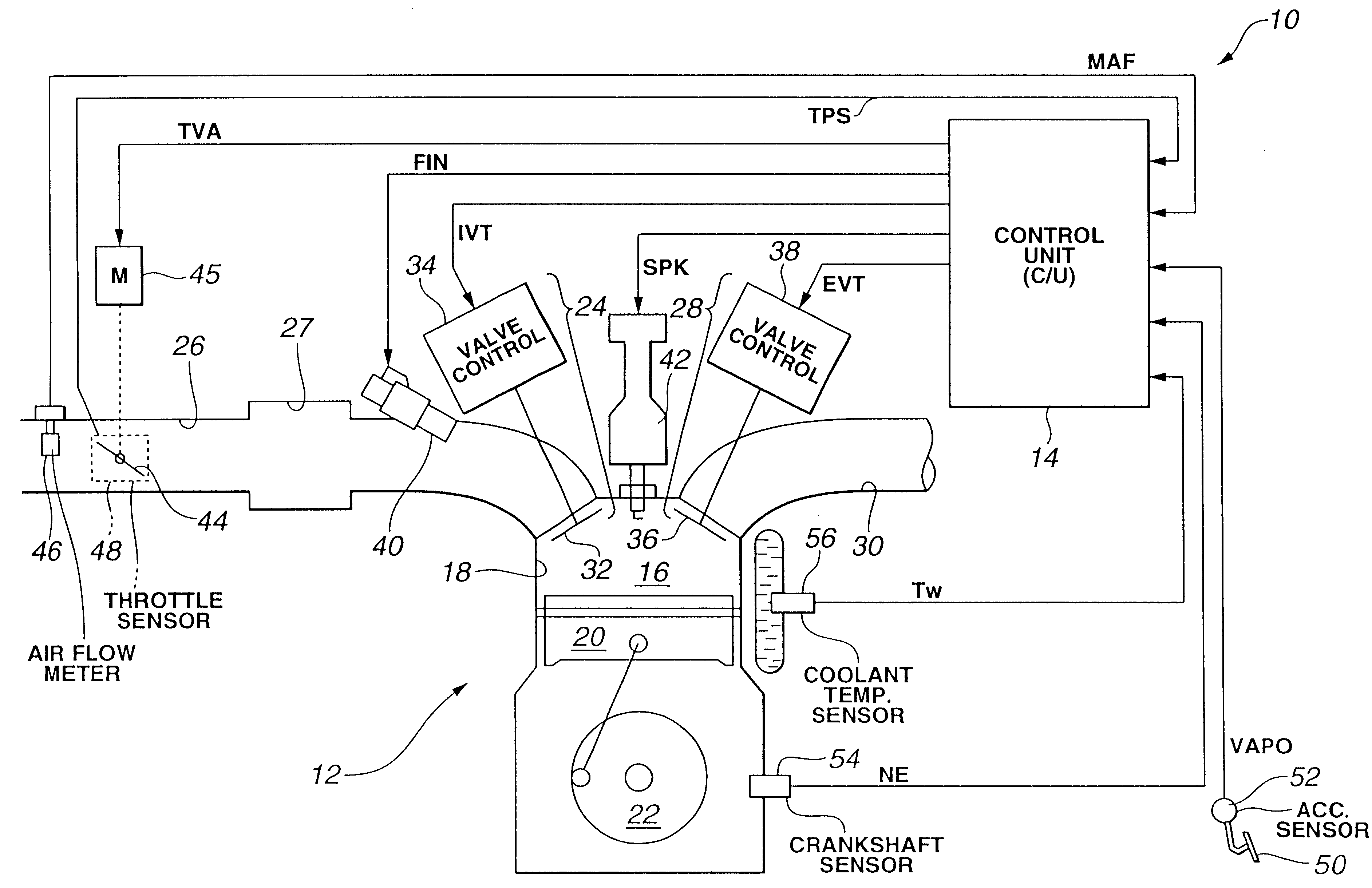
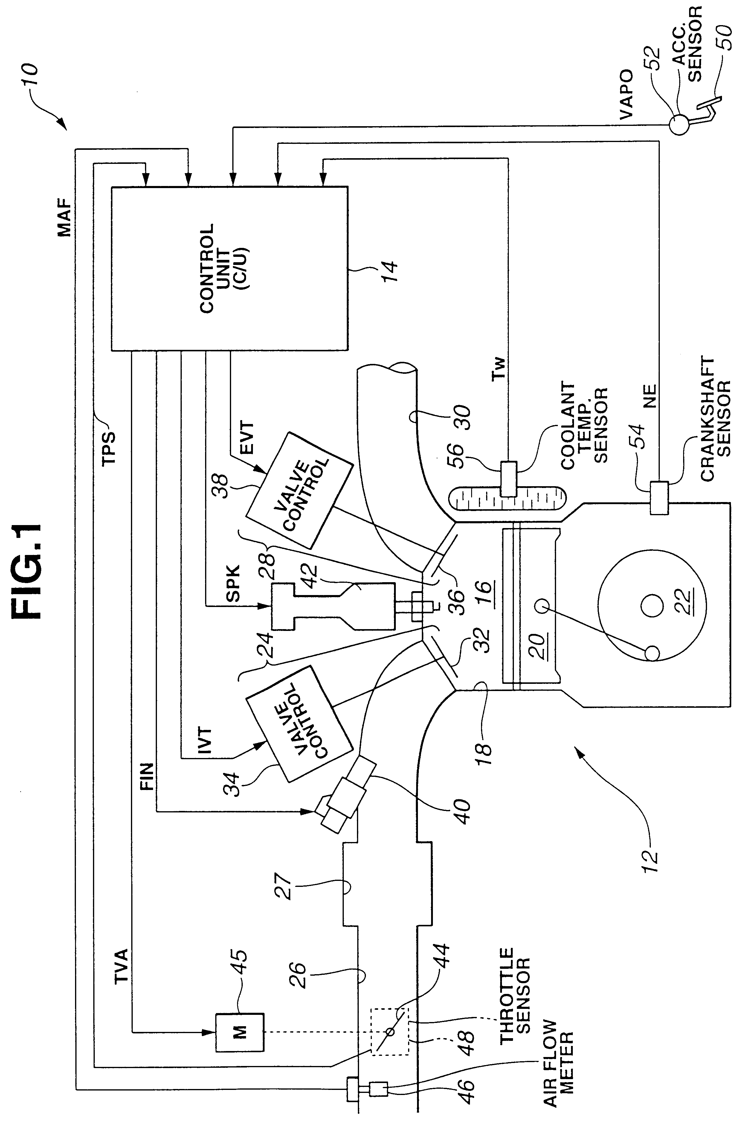
FIG. 1 is a block diagram illustrating operation of a system or method for controlling intake air by variable intake valve timing with response performance adjustment according to the present invention. System 10 includes an internal combustion engine, indicated generally by reference numeral 12, in communication with a control unit (C / U) 14. As schematically shown in FIG. 1, engine 12 has at least one combustion chamber 16 defined within a cylinder 18 by a reciprocating piston 20 operatively connected to a crankshaft 22. Combustion chamber 16 is provided with intake means 24 together with an intake manifold 26, including a collector 27, and exhaust means 28 together with an exhaust manifold 30. Intake means 24 include at least one intake valve 32, each driven by a variable valve control 34. Exhaust means 28 include at least one exhaust valve 36, each driven by a variable valve control 38. Fuel is injected into combustion chamber 16 through an injection nozzle 40. A spark plug 42 pr...


PUM


Abstract

A system and method control intake air of an internal combustion engine. The engine has at least one combustion chamber provided with intake valves together with an intake manifold provided with a throttle valve. The opening and closure timings of the intake valves are adjustable entirely independently by electromagnetic drivers from the crankshaft position to control the amount of intake air supplied to the combustion chamber. The system and method provide a response adjustment to variable valve timing and throttle valve position controls of the intake valves for unthrottled intake air control.

Description

1. Field of the InventionThe present invention relates to a system and method for controlling intake air to an internal combustion engine by unthrottled intake air control.2. TerminologyEngine DisplacementThis is used herein to mean the sum of displacements of all of cylinders of an engine. "Engine displacement" and "displacement of an engine" are synonyms. In the description, the reference character "VOL#" is used to represent the "engine displacement".3. Description of Related ArtJP-A 8-200025 discloses a system for controlling electromagnetic drivers (EMDs) for intake and exhaust valves provided per each combustion chamber of an internal combustion engine. According to this system, an electronic control unit (ECU) controls valve timings of intake and exhaust valves independently from the crankshaft position and speed in one of predetermined schedules fit for various engine operation ranges. The ECU identifies which one of the various engine operation ranges against varying engine...

Claims


Application Information

Patent Timeline
Patent Type & Authority Patents(United States)
IPC IPC(8): F02D41/00F01L9/04F01L9/20F02D13/02
CPCF01L9/04F02D13/0215F02D13/0234F02D41/0002F02D13/0253F01L2201/00F02B2275/32Y02T10/42F02D2041/001F02D2041/002Y02T10/18Y02T10/142Y02T10/12Y02T10/40F01L9/20
Inventor ARAI, MASAHIRONAGAISHI, HATSUO
Owner NISSAN MOTOR CO LTD
Why Eureka
Try Eureka