Touch panel device

a technology of touch panel and observer side, which is applied in the direction of mechanical pattern conversion, instruments, computing, etc., can solve the problems of poor insulation, difficult wiping of transparent insulating liquid 95 or the like, and difficulty in suppressing the reflection of a light made incident from the observer side of the touch panel

Inactive Publication Date: 2003-04-29
NISSHA PRINTING COMPANY
View PDF9 Cites 91 Cited by
  • Summary
  • Abstract
  • Description
  • Claims
  • Application Information

AI Technical Summary

Benefits of technology

For example, FIGS. 11 and 12 are a cross-sectional side view and a plan view, respectively, showing a touch panel device according to a fifth embodiment of the present invention. In the fifth embodiment, a part of the upper 46 of which portion corresponding to the upper surface of the touch panel 42 with an outer package 46 of which portion corresponding to the upper a surface of the touch panel 42 is partially removed sa shown with reference numeral 49 in FIG. 11. In this fifth embodiment, the exposed portion of the upper surface of the touch panel 42 includes at least the touch panel operation area 9 (see FIGS. 5 and 6). The aforementioned outer package 46 is constituted such that the outer package body 46a is constituted by deforming a film made of a synthetic resin, rubber, or metal into a rectangular parallelepiped box shape and the inside portion of the outer package body 46a housing the touch panel 42 is sealed by tightly adhering the outer package body 46a and the upper surface of the touch panel 42 with a sealing material 47 for sealing so as to enclose the peripheries of the outer package body 46a and the exposed portion of the upper surface of the touch panel 42 in a frame shape. The sealing material 47 may also be provided on the side surface of the touch panel 42, but can fulfill its sealing function when provided at least outside the operation area 9 on the upper surface of the touch panel 42 in a frame shape. Since liquid leakage is prevented at the portion where the sealing material 47 is disposed, there is no problem even if the outer package body 46 such as a film or the like and the touch panel 42 are not adhered tightly. Also, at least the portion of the outer package 46 corresponding to the operation area on the lower surface of the touch panel 42 needs to be transparent, but there is no problem even if other portion may be opaque.
FIGS. 13 and 14 are a cross-sectional side view and a plan view, respectively, showing a touch panel device according to a sixth embodiment of the present invention. In the sixth embodiment, a part of the upper surface and a part of the lower surface of the touch panel 42 are exposed by enclosing the touch panel 42 with an outer package 56 in which a part of a portion of the outer package body 46a in the fifth embodiment corresponding to the lower surface of the touch panel 42 is removed as shown with reference numeral 58 in FIG. 13. In this sixth embodiment, the exposed portions of the upper surface and the lower surface of the touch panel 42 include at least the touch panel operation area 9 (see FIGS. 5 and 6). The outer package 56 is constituted such that the outer package body 56a is constituted by deforming a film made of a synthetic resin, rubber, or metal into a rectangular parallelepiped box shape and the inside of the outer package body 56a housing the touch panel 42 is sealed by tightly adhering the outer package body 56a and the upper surface of the touch panel 42 to each other so as to enclose at least the peripheries of the outer package body 56a and the exposed portions of the upper surface and the lower surface of the touch panel 42 in a frame shape with a sealing material 57. The sealing material 57 may also be provided on the side surface of the touch panel 42, but can fulfill its sealing function when provided at least outside the operation areas 9 on the upper surface and the lower surface of the touch panel 42 in a frame shape. Since liquid leakage is prevented at the portion where the sealing material 57 is disposed, there is no problem even if the outer package body 56a such as a film or the like and the touch panel 42 are not adhered tightly. Also, there is no problem even if the outer package 56 is opaque.

Problems solved by technology

However, in cases where a touch panel device is used under a severe. environment or the like, the transparent insulating liquid 95 sealed in the touch panel is exuded outside at the portion where the upper electrode film 91 and the lower electrode body 92 of the touch panel are adhered, causing leakage.
Also, the transparent insulating liquid 95 leaks from a damaged portion such as a crack or the like when the touch panel is damaged in the cases where too strong pressure is applied when an input is made, the touch panel is dropped or an external pressure is applied to the touch panel.
In the case where such liquid leakage occurs, it becomes difficult to suppress reflection of a light made incident from the touch panel observer side or improve the visibility of the liquid crystal screen.
Further, the upper electrode film of the touch panel bends depending on the degree of liquid leakage, thereby making it likely that poor insulation occurs.
Also, since the leaking insulating transparent liquid 95 is put into contact with a constituent member other than the touch panel such as, for example, a circuit board or the like, a failure of the constituent member is caused or the aftertreatment when the damaged touch panel is exchanged, for example, wiping of the transparent insulating liquid 95 or the like becomes difficult.

Method used


Image

  • Touch panel device
  • Touch panel device
  • Touch panel device

Examples


Embodiment Construction

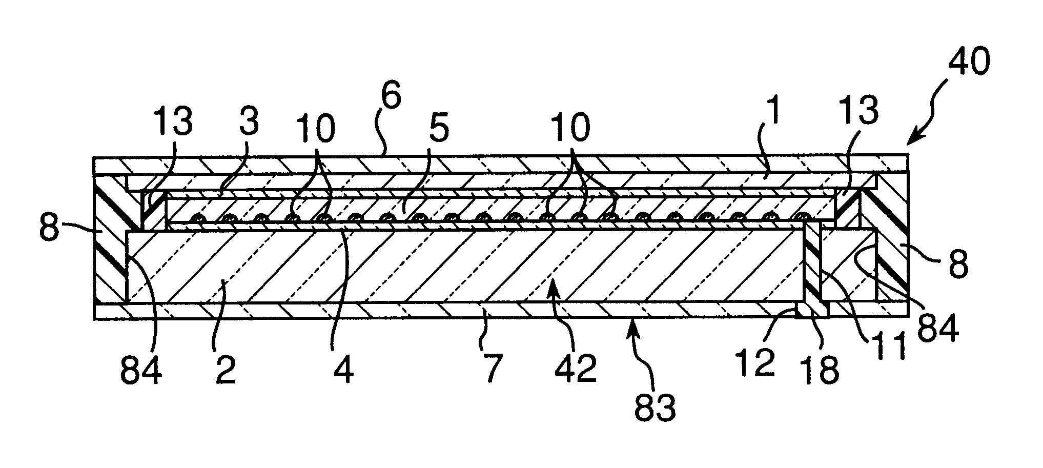
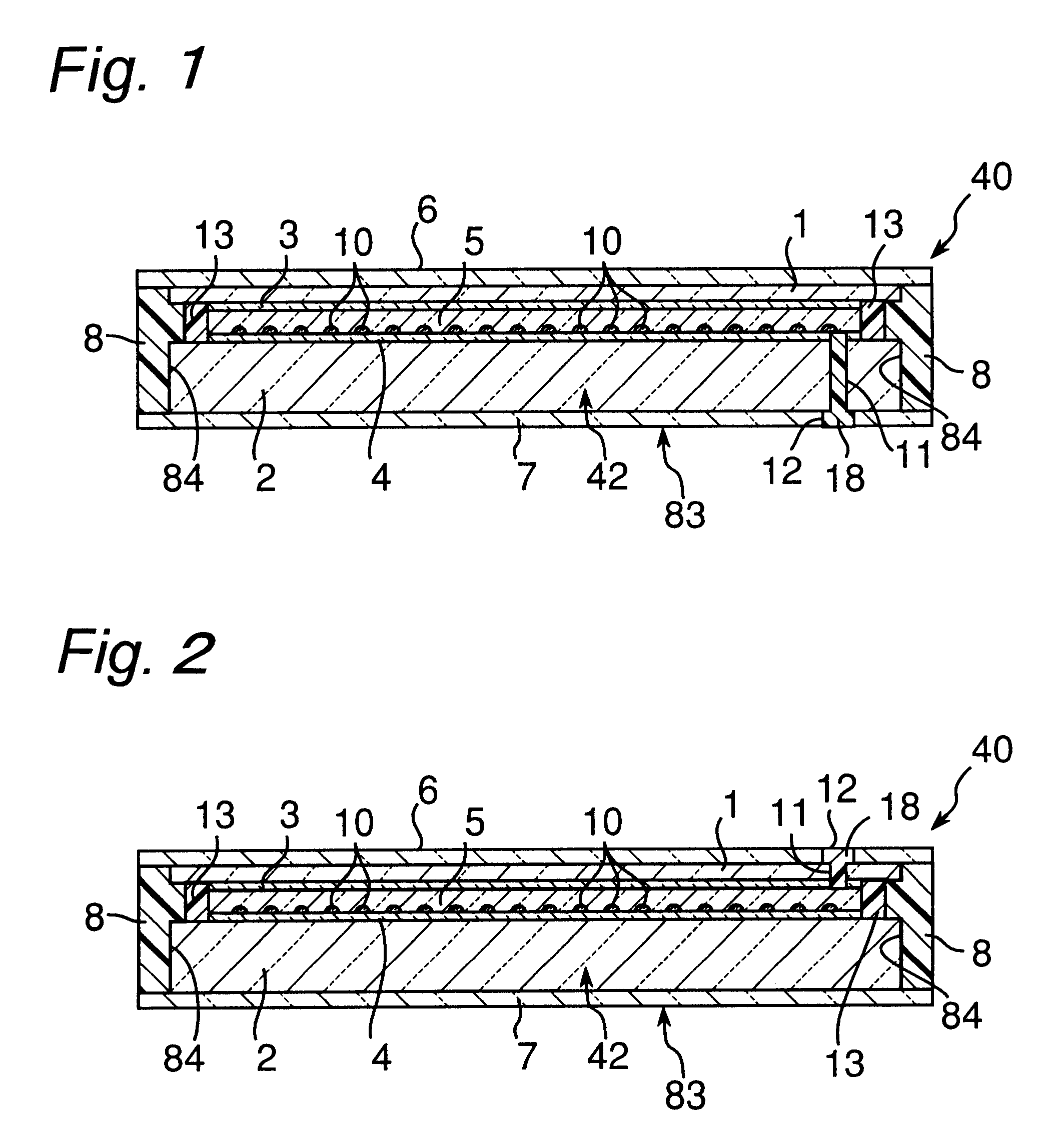
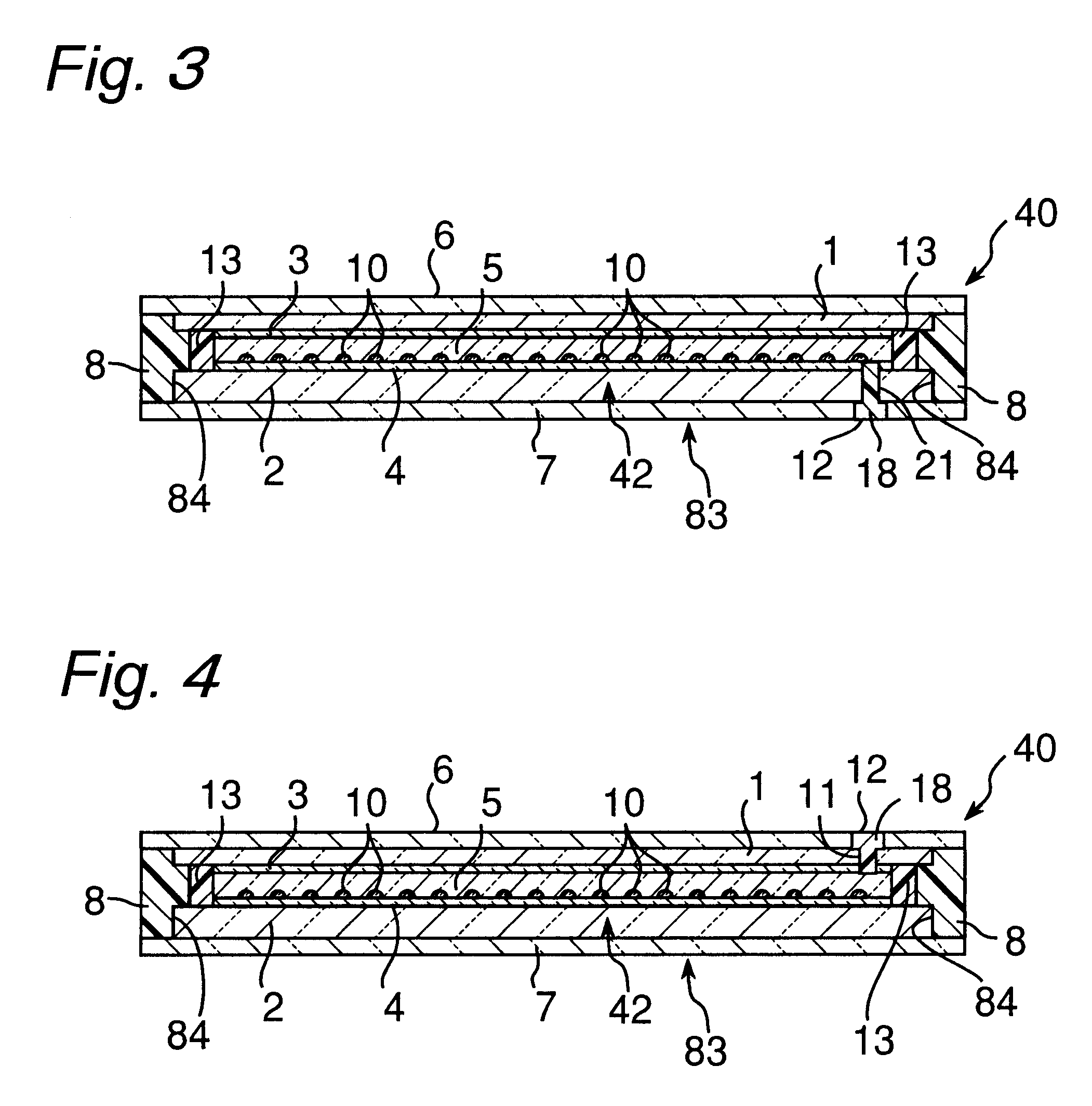
touch panel was prepared by using a double-face adhesive tape to adhere the peripheries of an upper electrode film having a thickness of 150 .mu.m on the lower side of which an upper transparent electrode made of indium oxide / tin oxide is formed and a lower electrode body made of a glass plate having a thickness of 0.7 mm on the upper side of which a lower transparent electrode made of indium oxide / tin oxide is formed, which are opposed to each other, via spacers (area concentration: 0.01%, height: 3 .mu.m) made of a transparent resin.

A polyester film that has sides, each being 3 mm longer than a side of the upper surface of this touch panel, and has been subjected to a low-reflection treatment by mat coating is adhered on the upper surface of the touch panel and a polycarbonate film having a thickness of 0.3 mm that has sides, each being 3 mm longer than a side of the lower surface of the touch panel, was adhered on the lower surface of the touch panel. Subsequently, a sealing mate...


PUM


Abstract

The sides of a touch panel are entirely covered with and sealed in an outer package. The touch panel includes a transparent insulating liquid that is sealed in a space formed by adhering an upper electrode film and a lower electrode body at edges thereof. The transparent insulating liquid transparently shows or exposes at least an operation area of the touch panel.

Description

The present invention relates to a resistor-film type touch panel capable of inputting information with a finger or pen positioned in front of a display device such as a liquid crystal display device (LCD) for use in an electronic notebook, a personal computer, or the like; or CRT or the like and, particularly, a highly practical touch panel device subjected to a treatment for preventing leakage of a transparent insulating liquid sealed in the touch panel.As a conventional touch panel, as shown in FIG. 23, the one in which a transparent insulating liquid 95 is sealed in a space obtained by adhering an upper electrode film 91 and a lower electrode body 92 at their edges with an adhesive agent, a double-face adhesive tape 103, or the like so as to suppress reflection of a light made incident from the touch panel observer side and improve the visibility of the liquid crystal screen (see Japanese Utility Model Laid-open Publication No. 59-98528 and Japanese Patent Laid-open Publication ...

Claims


Application Information

Patent Timeline
Patent Type & Authority Patents(United States)
IPC IPC(8): G06F3/033G06F3/041
CPCG06F3/041G06F3/045G06F3/0412
Inventor TAKAHATA, KAZUHIKOHASHIMOTO, TAKAONISHIKAWA, KAZUHIROKIRIMURA, HIROSHI
Owner NISSHA PRINTING COMPANY
Why Eureka
Try Eureka