Gas insulated switchgear

a switchgear and gas insulation technology, applied in switchgear arrangements, non-enclosed substations, substations, etc., can solve the problems of long length of circuit breaker units in an arrangement direction, long connection bus, and increase in installation area according to the number of circuit lines

Inactive Publication Date: 2003-05-06
HITACHI LTD
View PDF24 Cites 12 Cited by
  • Summary
  • Abstract
  • Description
  • Claims
  • Application Information

AI Technical Summary

Problems solved by technology

However, in such a construction, the connection bus is very long because the connection bus is stretched around in horizontal and vertical directions.
However, in such a construction, an installation area increases according to increase in the number of circuit lines and it becomes necessary to disassemble and move each unit in the case where circuit lines are added.
However, in such a construction...

Method used


Image

  • Gas insulated switchgear
  • Gas insulated switchgear
  • Gas insulated switchgear

Examples


Embodiment Construction

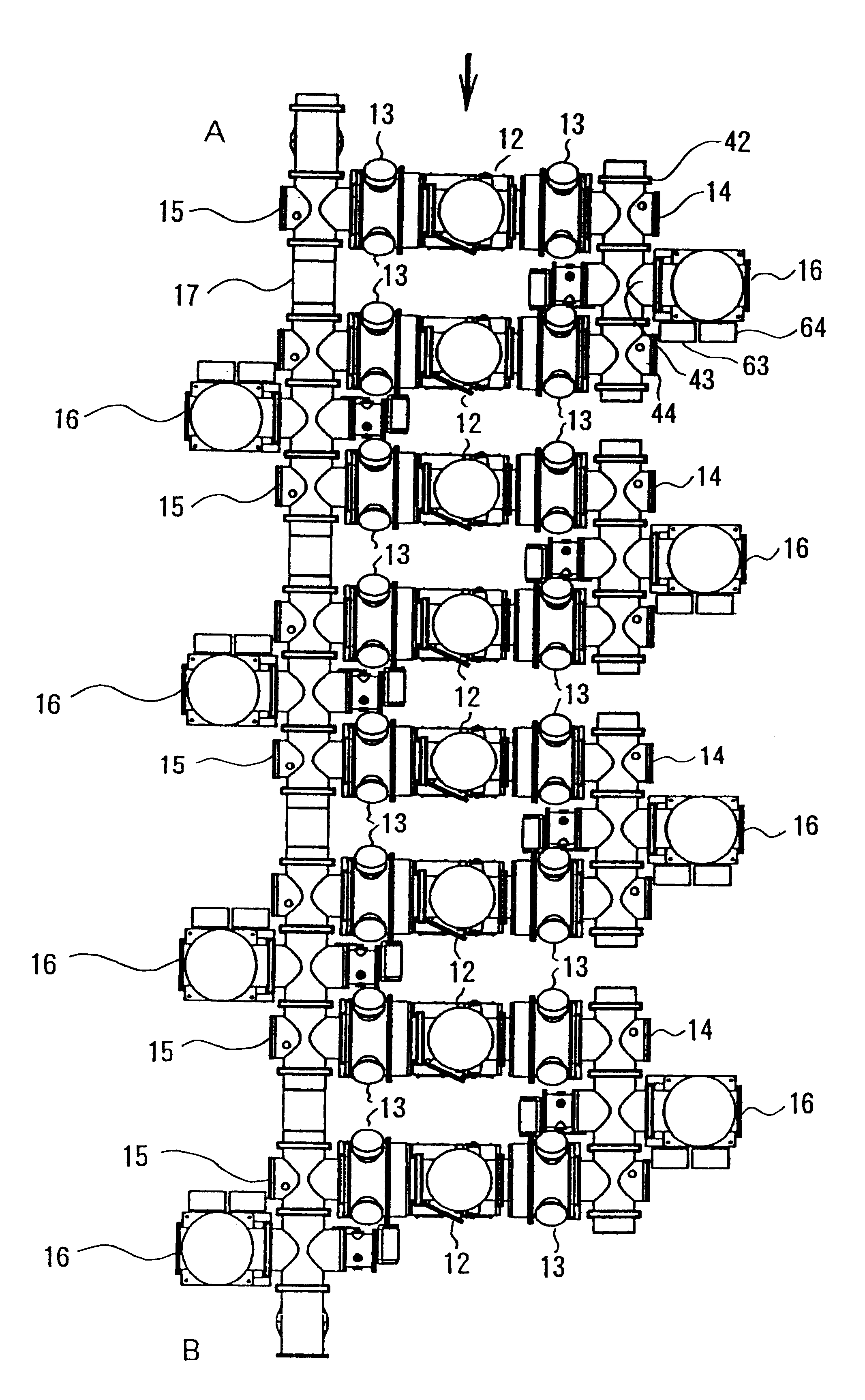
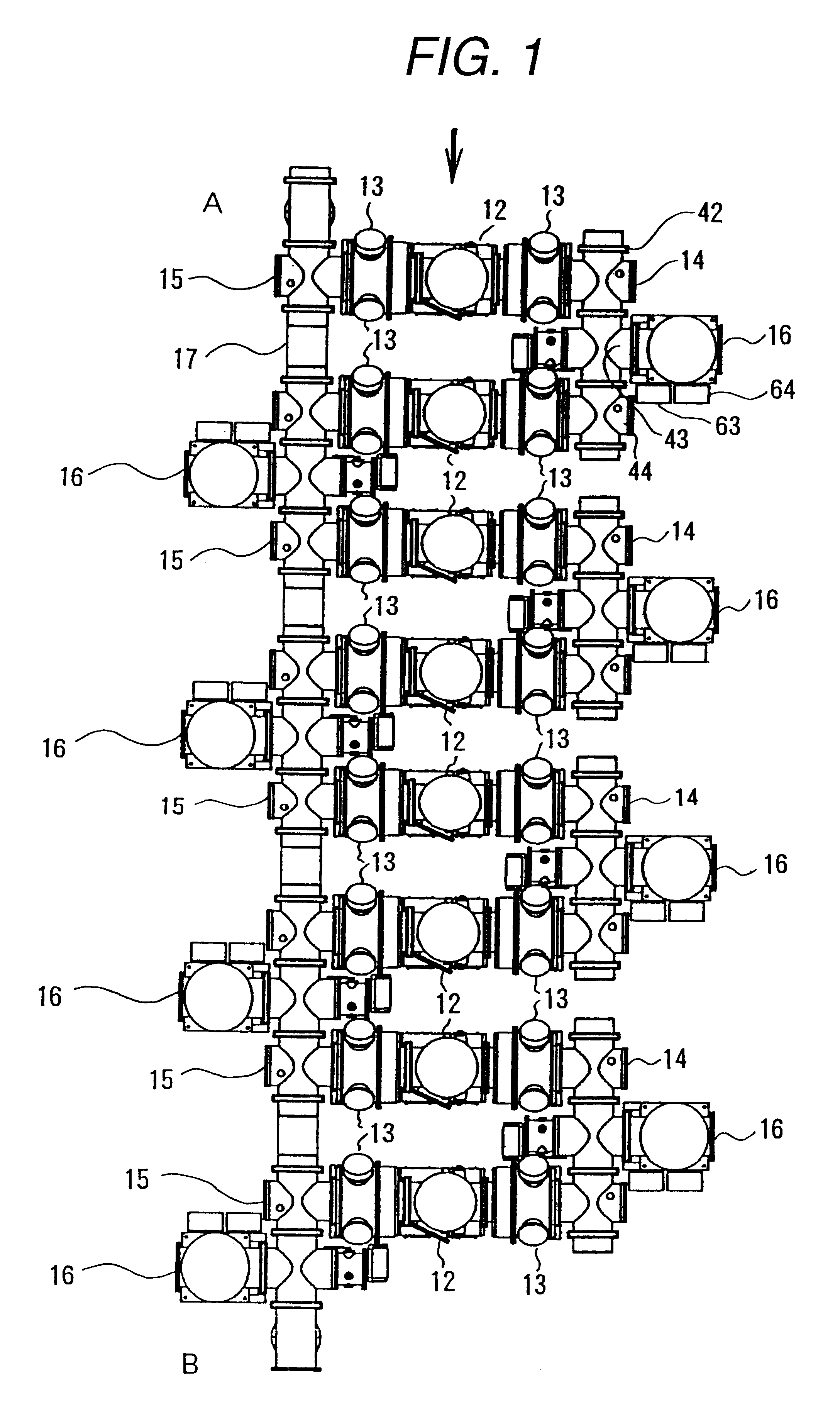
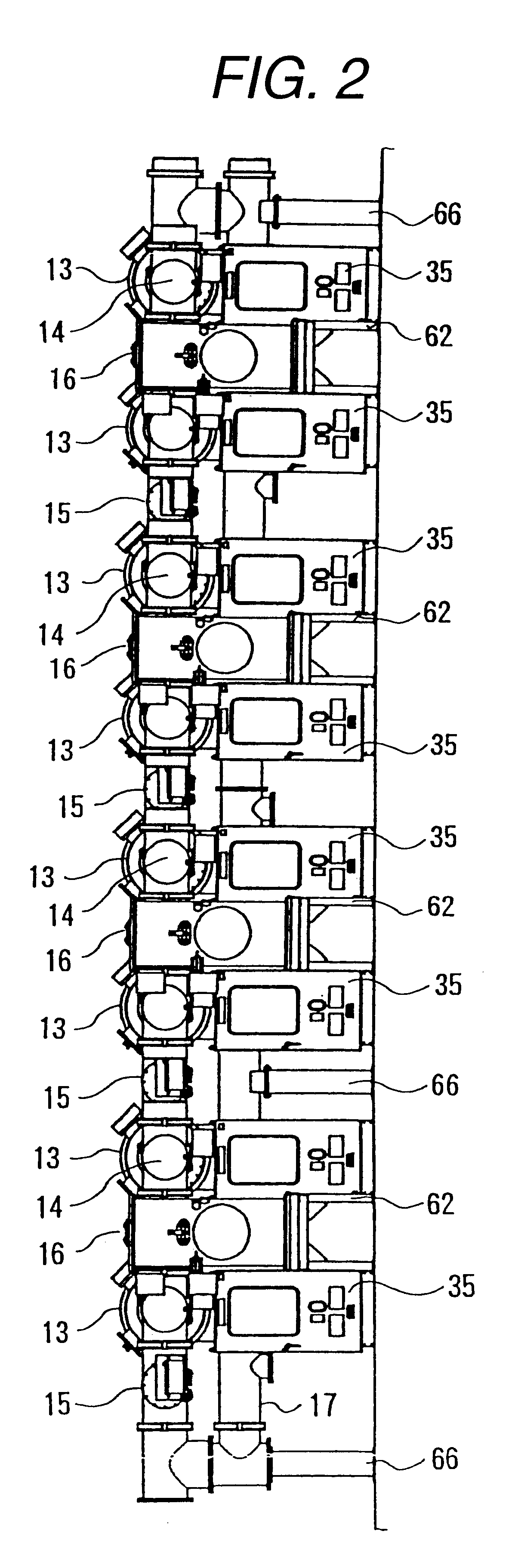
FIG. 15 shows a circuit construction of a ring bus arrangement type gas insulated switchgear of an embodiment of the present invention.

1 denotes a circuit breaker, and earth devices 2 are arranged on both sides of the circuit breaker 1. Current transformers 3 are connected to the earth devices 2, respectively, on the sides opposite to the circuit breaker 1, and disconnecting switches 4 are connected to the current transformers 3, respectively, on the sides opposite to the earth devices 2. In the present embodiment, a plurality of series circuits, in each of which the circuit breaker 1, the earth devices 2, the current transformers 3 and the disconnecting switches 4 are electrically connected in series, are arranged perpendicularly to a direction of the connection thereof, that is, they are arranged in one row.

The plurality of series circuits are connected by first connection buses 5 and second connection buses 6. In the present embodiment, a plurality of the first connection buses 5...


PUM


Abstract

In order to shorten the length of connection buses and reduce a cost, in the present invention, a plurality of T-branched circuit breaker units 12 are arranged in a direction perpendicular to the T-branch direction, and the plurality of circuit breaker units 12 are connected by first connection bus units 14 and second connection bus units 15 in series alternately in a rectangular wave shape on a horizontal plane of approximately the same height as the T-branch portions of the circuit breaker units 12. Thereby, first connection buses 5 and second connection buses 6 are stretched around on the horizontal plane of the same height as the T-branch portions of the circuit breaker units 12, but not stretched around in an up and down direction. Therefore, the length of the connection buses can be reduced, and the cost also can be reduced.

Description

The present invention relates to a ring bus arrangement type gas insulated switchgear.BACKGROUND OF THE ARTIn a conventional ring bus arrangement type gas insulated switchgear, a plurality of circuit breaker units and a plurality of line side units are oppositely arranged and connection bus units are arranged between the circuit breaker units and the line side units, oppositely arranged, as disclosed in JP A 57-211915, JP A 59-6706, JP A 3-245706 or JU A 5-33610. However, in such a construction, the connection bus is very long because the connection bus is stretched around in horizontal and vertical directions.Further, there are a ring bus arrangement type gas insulated switchgear in which a plurality of circuit breaker units and a plurality of line side units are alternately arranged in loop as a ring bus arrangement type gas insulated switchgear disclosed in JP A 58-75413 or JP A 9-261810, and a ring bus arrangement type gas insulated switchgear in which connection bus units each ...

Claims


Application Information

Patent Timeline
IPC IPC(8): H02B13/035
CPCH02B13/0352H02B5/06H02B13/035
Inventor TAKAHOSHI, MASAHIROTSUZURA, KEIICHISHINOHARA, RYOICHIHENMI, REIAIKO, YORIYUKIITO, SHUNJI
Owner HITACHI LTD
Why Eureka
Try Eureka