Use of magneto-resistive sensors for borehole logging

a technology of magneto-resistive sensors and boreholes, which is applied in the field of use of magneto-resistive sensors for measuring the diameter of boreholes, and can solve the problems of bulky and expensive, large lvt/lvdt sensors, and increased hysteresis effects

Inactive Publication Date: 2003-05-13
BAKER HUGHES INC
View PDF20 Cites 61 Cited by
  • Summary
  • Abstract
  • Description
  • Claims
  • Application Information

AI Technical Summary

Problems solved by technology

New potentiometer devices exhibit small hysteresis effects but as the devices age, the hysteresis effects becomes more severe as potentiometers begin to wear.
If larger distances are to be sensed, LVT / LVDT sensors become very large and very expensive.
High pressure / temperature versions are possible but they are bulky and expensive.

Method used


Image

  • Use of magneto-resistive sensors for borehole logging
  • Use of magneto-resistive sensors for borehole logging
  • Use of magneto-resistive sensors for borehole logging

Examples


Embodiment Construction

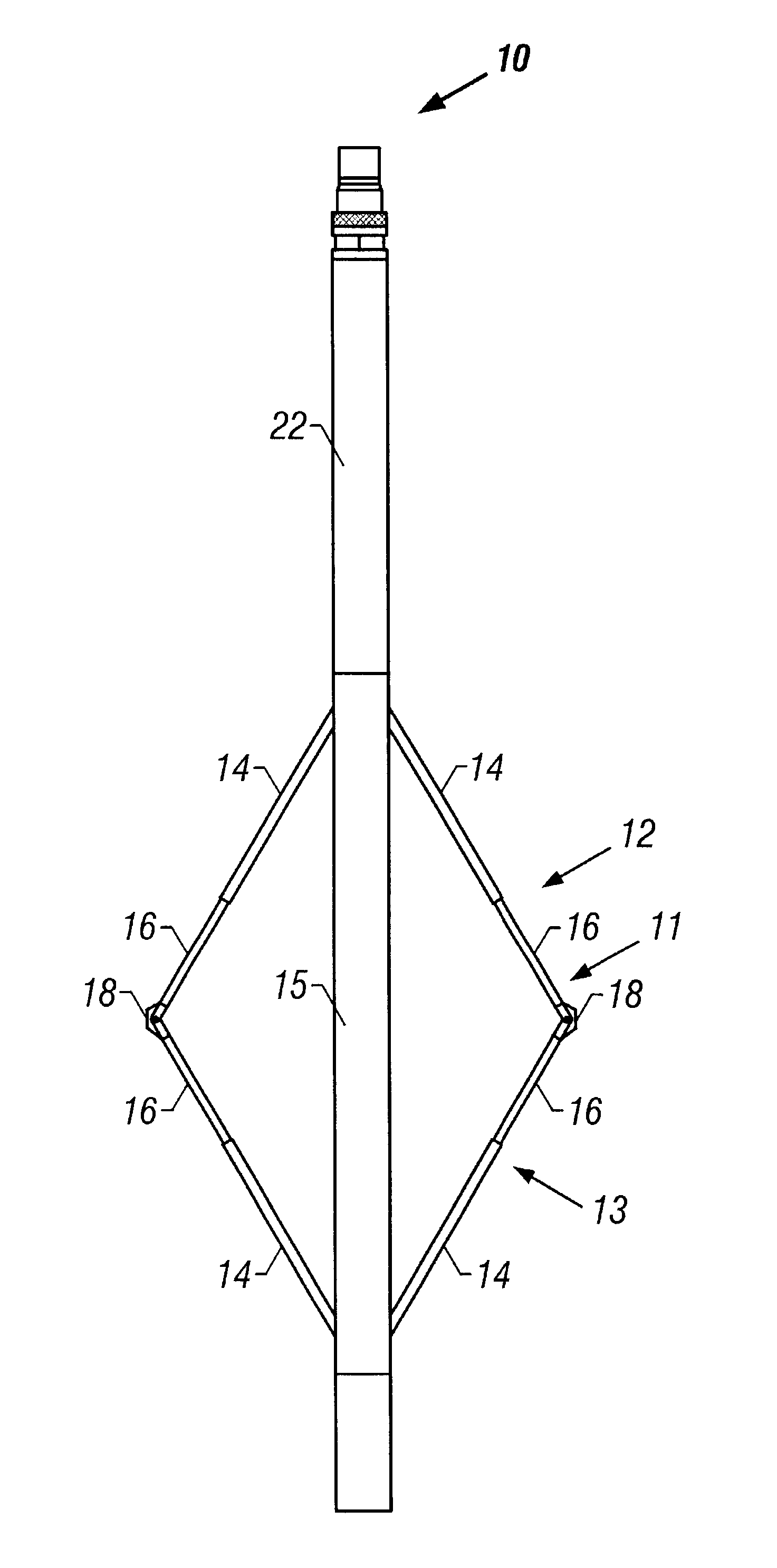
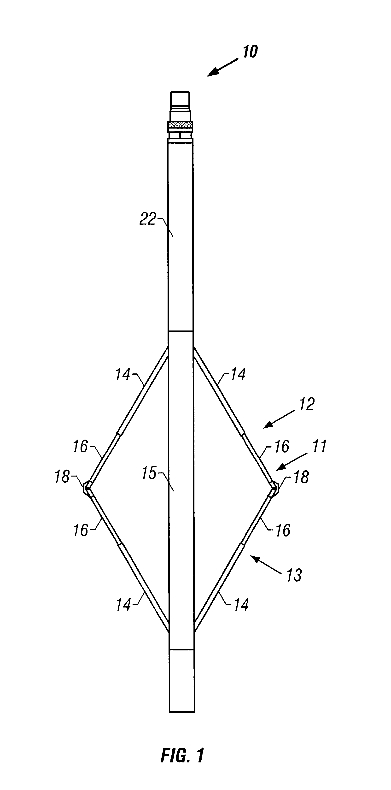
Turning now to FIG. 1, the present invention provides a six-arm caliper instrument comprising six radial extensive, equally spaced caliper arms, each of which independently enables an independent radius measurement of the borehole in which the caliper instrument is deployed. The six-arm caliper instrument 10 provides six independent arms 11, each of which comprises two spring-loaded telescopically extensible sections 14 and 16, as illustrated in FIG. 1. The caliper instrument of the present invention enables logging of independent borehole radius measurements associated with each caliper arm, while the caliper instrument traverses the bore hole. Borehole radius measurements are taken and logged during ingress and egress of the caliper instrument, and while the caliper instrument is descending or ascending the borehole. The preferred caliper arm 11 comprises two spring-loaded telescopic sections 14 and 16, which enable the caliper arm sections to extend or compress to conform to the ...


PUM


Abstract

A downhole caliper instrument utilizing a magneto resistive sensor to determine the position of a caliper arm which extends to touch the surface of the borehole wall.

Description

1. Field of the InventionThe present invention relates to the use of magneto resistive sensors for measuring the diameter of a borehole.2. Background of the Related ArtDown hole distance and bore hole radius measurements have previously been performed with instruments using potentiometers, linear voltage transformer (LVT) sensors or linear voltage differential transformer (LVDT) sensors. Potentiometers are resistors with an attached position indicating slider. The slider contacts the resistor at any point between the potentiometer ends. The mechanical position of the slider determines the resistance between the slide and the ends of the potentiometer. A position measurement is thereby possible, by measuring either the resistance or the voltage between the slider and one of the potentiometer ends.In down hole logging instruments, potentiometers are typically placed inside of an oil-filled container, so that the mechanical movement of the slider is not influenced by the bore hole pres...

Claims


Application Information

Patent Timeline
Patent Type & Authority Patents(United States)
IPC IPC(8): E21B47/08E21B47/00G01B7/12G01B7/13
CPCG01B7/13E21B47/08
Inventor LECHEN, HELMUT
Owner BAKER HUGHES INC
Why Eureka
Try Eureka