Belt, especially conveyer belt and method for manufacturing same

a conveyer belt and belt technology, applied in the field of conveyer belts, can solve the problems of disturbance noise and particularly negligible additional effort, and achieve the effect of reducing the noise level

Inactive Publication Date: 2003-05-13
NORDDEUTSCHE SEEKABELWERKE AG
View PDF21 Cites 41 Cited by
  • Summary
  • Abstract
  • Description
  • Claims
  • Application Information

AI Technical Summary

Benefits of technology

is therefore to create a belt, especially a conveyer belt, which results in a lower level of noise being generated.
For a belt comprising a load-carrying traction means and at least one guidance means for directing the conveyer belt on the transport path, it is expedient to have only the guide means provided with a reduced friction value at least on part of its outer surface. This proves sufficient for reducing the generation of noise by the conveyer belt because the deflection of the conveyer belt along the conveying path occurs via a single or, if required, a plurality of guide means of the conveyer belt, with most of the disturbing noise being generated by this deflection. The traction means of the belt then requires no modification at all.
The coating preferably takes place by means of a synthetic web applied externally to at least one part of the core material of the belt. This type of coating can be applied easily, ensuring a permanent bond with the core material of the belt. However, it is also conceivable to spray, flock coat or extrude the coating of synthetic material with a lower friction value onto the core material with a greater friction value.
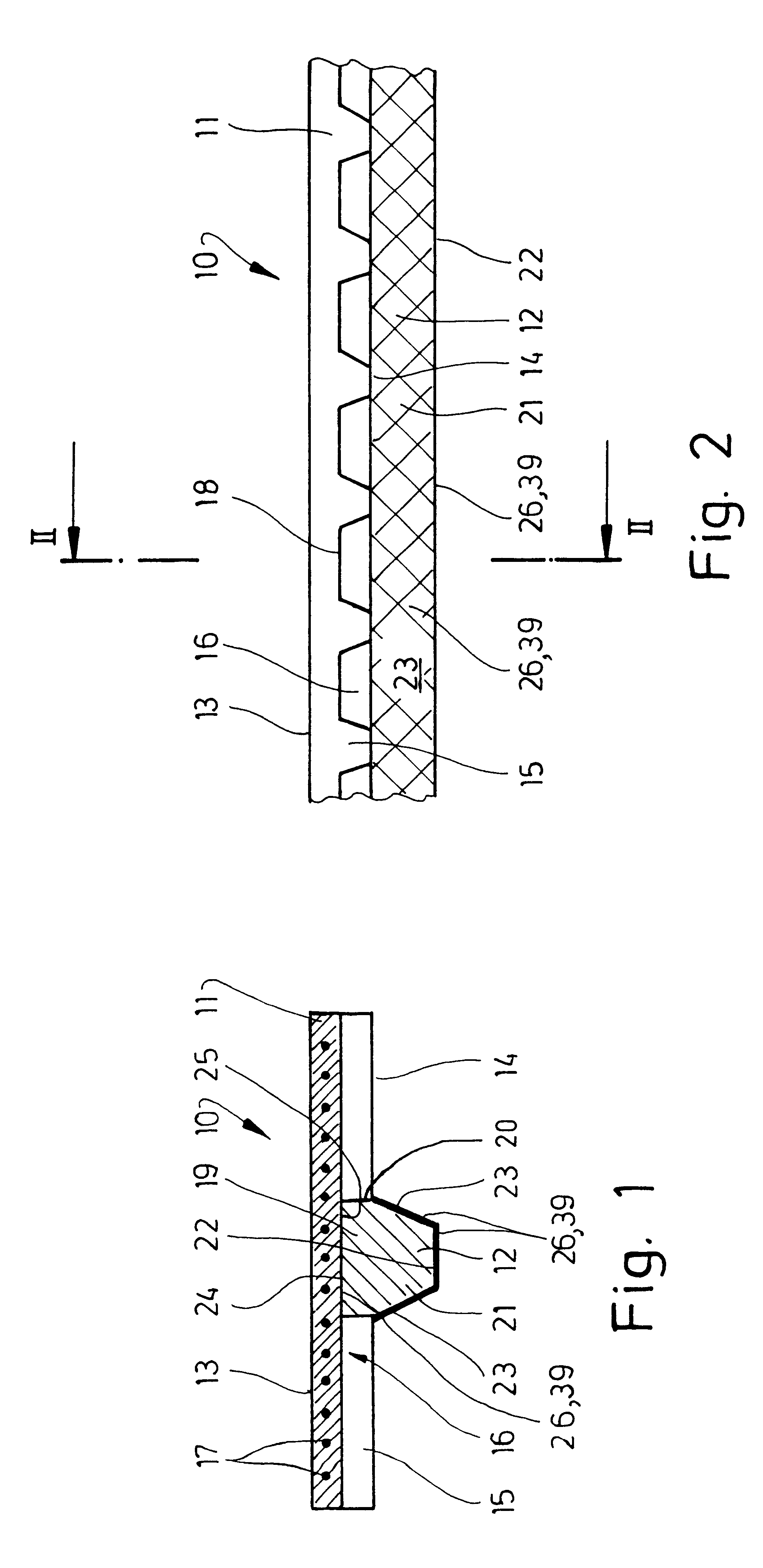
According to a further development of the belt, a profile is to be given to at least the guide surfaces of the guide means. This profile can be formed by grooves and / or projections of an arbitrary cross-section. But it is also conceivable to have provided a web-like profile made of strands, in particular, criss-crossing strands. By giving a profile to at least the guide surfaces of the guide means, a reduction of the bearing surfaces on the rollers, drums or the like used to deflect the belt is achieved. In conjunction with the coating of reduced friction value, which in particular also extends across the region of the projections, grooves and / or strands, this arrangement results in a particularly effective reduction of unpleasant noises.
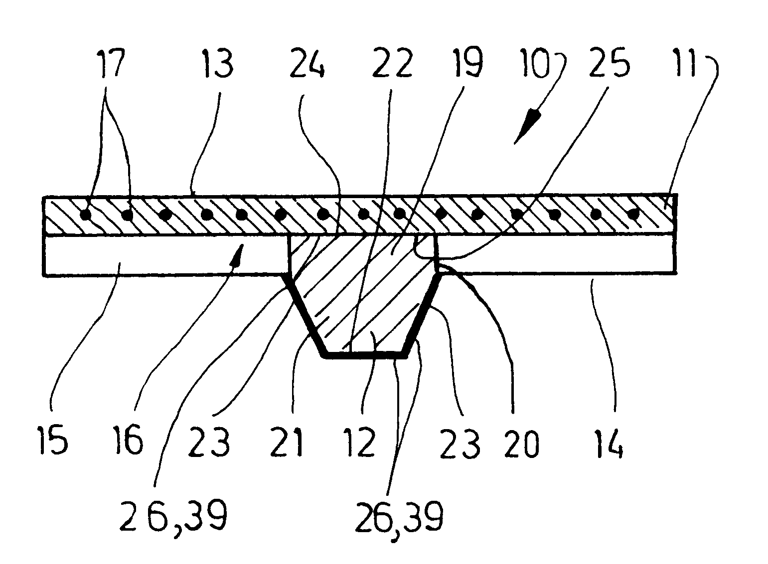
As an alternative to the shown exemplary embodiment, the guide means 12 can also be disposed on a differently configured traction means, such as a flat belt. It is also conceivable for the conveyer belt to have a plurality of, preferably parallel, guide means 12. Finally, the guide means 12 may exhibit different cross-sections. In particular, the guide section 21 of the guide means 12 must not be trapezoid in shape. It can also have a triangular-shaped cross-section or a semi-circular one. Ultimately, for belts which have only one traction means, and thus no guide means 12, the traction means itself can feature a reduced friction value along parts of its outer side by having a part of the traction means coated with an appropriate material
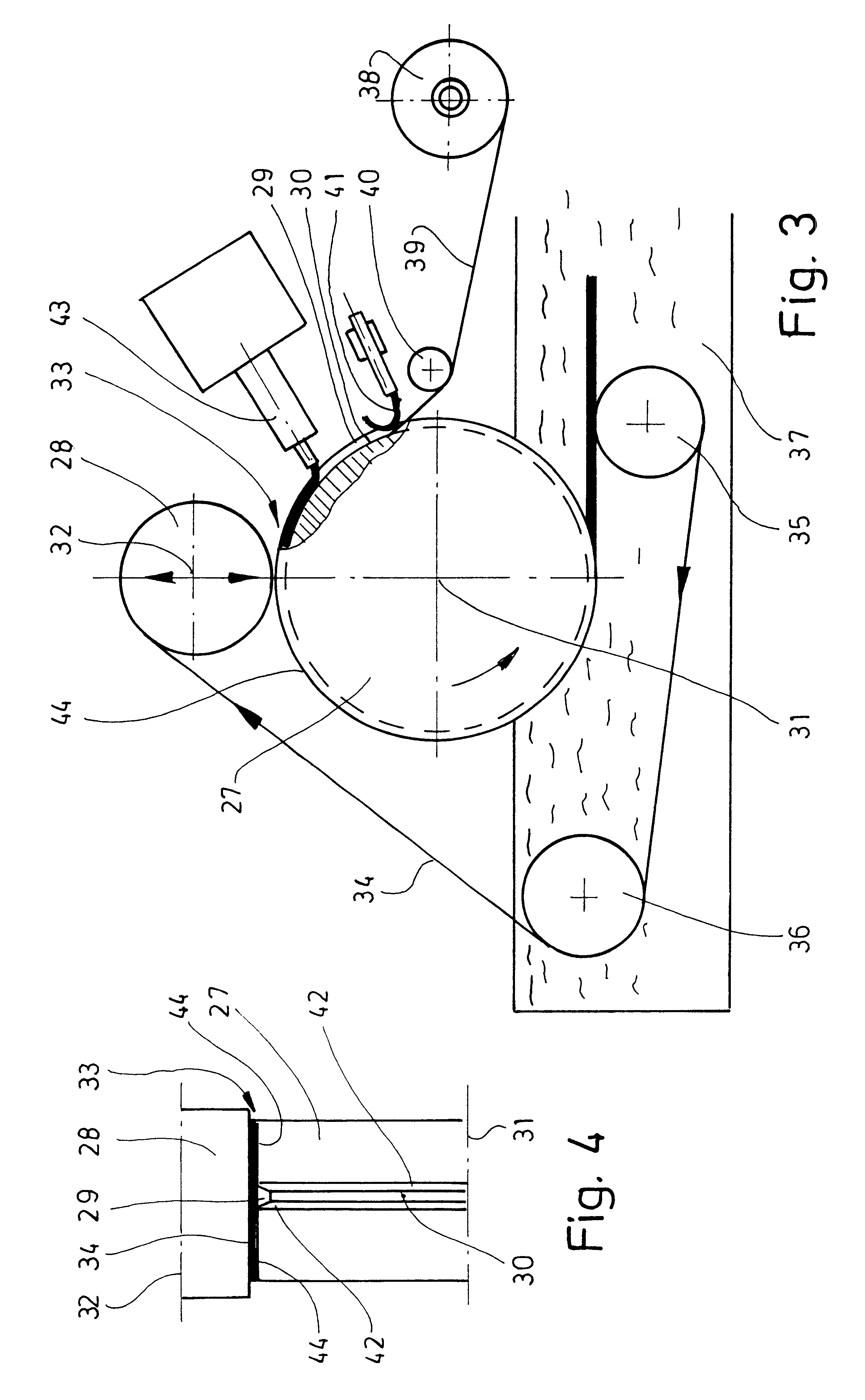
Due to the uniformly rotating form wheels 27 and 28 and a continuous forward movement of the tension belt 34, the polyamide web 39 and the free-flowing core material for the guide means 12 are conveyed further into the form gap 33. There the small form wheel 28 presses the material into the key groove 29, with excess material landing on the cylindrical surface shell 44 of the form wheel 27. After passing through the form gap 33, the surface shell 44 of the form wheel 27 is covered by the tension belt 34. This allows the polyamide web 39 and the core material for the guide means 12 to be lowered into the water bath 37 still sandwiched between the tension belt 34 and the form wheel 27. In the process, a cooling process, especially that of the core material, takes place for the formation of the guide means 12. After sufficient cooling, the tension belt 34 is deflected from the form wheel 27 and the completed guide means 12 can be led out of the key groove 29 of the form wheel 27. During the formation of the guide means 12 in the key groove 29 of the form wheel 27, the textured outer side of the polyamide web 39 for forming the coating 26 can be smoothed, which leads to a further-reduction of the friction value, above all that of the outer side of the coating 26.

Problems solved by technology

It has been established that disturbing noises arise in the regions where such a belt is deflected.
This additional effort is particularly negligible if the coating material is fed to the form device in a cold state.

Method used


Image

  • Belt, especially conveyer belt and method for manufacturing same
  • Belt, especially conveyer belt and method for manufacturing same
  • Belt, especially conveyer belt and method for manufacturing same

Examples


Embodiment Construction

The above figures, in particular FIGS. 1 and 2, show a belt which is more precisely a conveyer belt 10. The conveyer belt 10 shown here comprises a traction means 11 and a guide means 12. The traction means 11 serves mainly to transmit the driving forces of the conveyer belt 10. Objects to be transported can lie directly on a smoother top side 13 of the traction means 11. But generally the conveyer belt 10 is arranged below separate carrying means for receiving the objects to be transported. This may be arranged such that the conveyer belt 10 is frictionally-engaged to the underside of the preferably plate-shaped carrying means, which are not shown in the figures, lying against it with the top side 13 of the traction means 11, or is connected in a force-locking manner to the carrying means for transporting the objects, for example by means of screws or rivets.

The traction means 11 has a toothed-belt profile on its underside 14. In the shown exemplary example, the profile results fro...


PUM

PropertyMeasurementUnit
frictionaaaaaaaaaa
coefficient of frictionaaaaaaaaaa
shapeaaaaaaaaaa

Abstract

Conveyer belts (10) are deflected many times along a conveying path of the objects to be conveyed. It has been shown that unpleasant squeaking noises are generated in the region of this deflection between the guide means (12) of the conveyer belt (10) and guide rollers or guide drums.The invention is based on the knowledge that the squeaking noises are caused by the relatively high friction value of the material of the conveyer belt (10). The design according to the invention therefore proposes that at least the outer side of the guide means (12) of the conveyer belt (10) is provided with a coating (26) made from a material with a lower frictional value. As a result, it has been shown that undesirable squeaking noices can be effectively avoided.

Description

The invention relates to a belt, especially a conveyer belt, and a method for manufacturing a belt.PRIOR ARTBelts usually consist entirely or in large part of an elastic material with a proportionately high friction value (coefficient of friction). The high friction value is necessary in order to be able to transmit the greatest possible driving forces with the belt. Belts which are employed for conveying or transporting purposes, namely conveyer belts, are deflected along the conveying path by usually a rather large number of rollers or drums, thus being led around curves in the conveying plane. It has been established that disturbing noises arise in the regions where such a belt is deflected.The objective of the invention is therefore to create a belt, especially a conveyer belt, which results in a lower level of noise being generated.A belt which fulfills this objective has the features of claim 1. Accordingly, the outer side of the belt is provided at least partially with a redu...

Claims


Application Information

Patent Timeline
Patent Type & Authority Patents(United States)
IPC IPC(8): B29D29/00B29D29/06B65G15/36B65G15/60B65G15/64B65G15/32F16G1/28
CPCB29D29/06B65G15/32F16G1/28B65G15/64B65G15/36B65G2201/06
Inventor BASSE, HARTWIG
Owner NORDDEUTSCHE SEEKABELWERKE AG
Why Eureka
Try Eureka