
Garment carrying electronic devices

a technology for electronic devices and garments, applied in the field of garments, can solve the problems of device electrical connections exposed and vulnerable, and achieve the effect of relatively simple removal and/or replacement of devices

Inactive Publication Date: 2003-05-13
SIGNIFY HLDG BV
View PDF17 Cites 79 Cited by
  • Summary
  • Abstract
  • Description
  • Claims
  • Application Information

AI Technical Summary

Benefits of technology

It is accordingly an object of the present invention to provide a garment which addresses the problem of making removal and / or replacement of devices relatively simple.
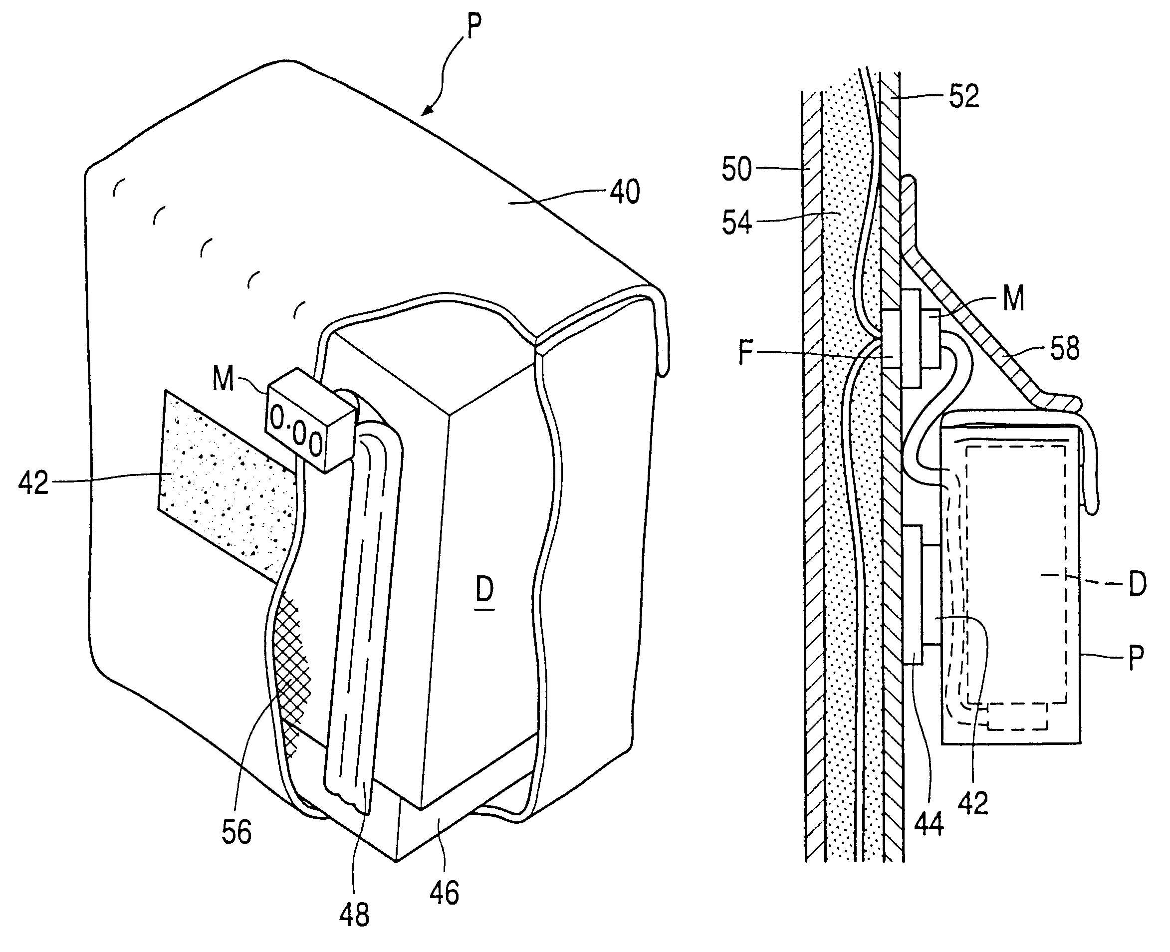
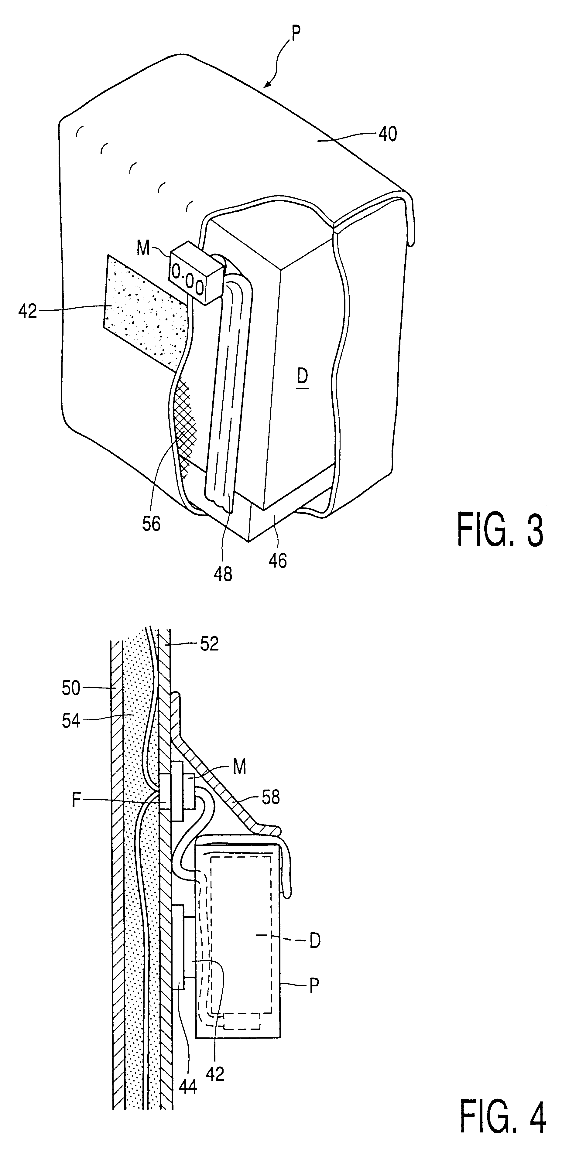
The aforesaid means to establish electrical connection may comprise a simple aperture in the pocket fabric cover to permit access to the device electrical connections, although this could leave the device electrical connections exposed and vulnerable. Preferably, however, the means to establish connection comprises an adaptor cable extending from within the pocket to outside, the end of the cable within the pocket having connector means enabling electrical connection to a device within the pocket and the outside end of the adaptor cable being provided with means enabling electrical connection to one or more of said electrical conductors. With such an arrangement, disconnection of the electrical device in the pocket may easily be accomplished without removal of the device from the pocket, as the adaptor cable, pocket, and electrical device could simply be removed as a single unit. To further facilitate this, the means enabling electrical connection between the outside end of the adaptor cable and one or more of said electrical conductors suitably comprises a matched plug and socket pair.

Problems solved by technology

The aforesaid means to establish electrical connection may comprise a simple aperture in the pocket fabric cover to permit access to the device electrical connections, although this could leave the device electrical connections exposed and vulnerable.

Method used


Image

  • Garment carrying electronic devices
  • Garment carrying electronic devices
  • Garment carrying electronic devices

Examples


Embodiment Construction

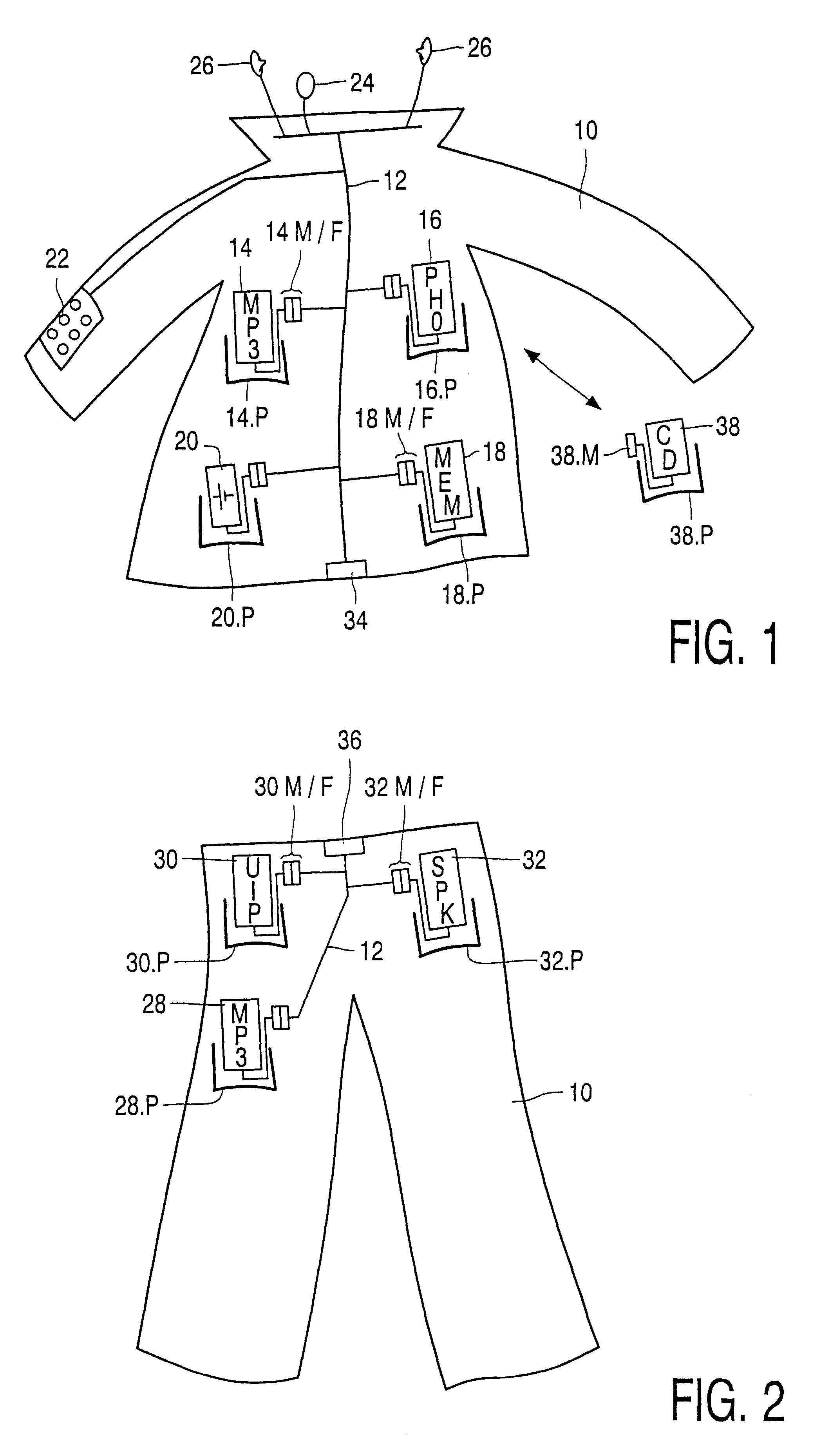
Starting with FIGS. 1 and 2, schematic representations of garments (for upper and lower body respectively) are shown hosting a plurality of interconnected electrical devices. It will be recognised that the form, function and style of the garment will generally have no bearing on the operation of the present invention other than requiring a capability to support two or more electrical devices (which may be in the form of separate components of a single device distributed around the garment).

Each garment comprises a fabric shell 10 hosting one or more electrical conductors, which may range in configuration from a single conductor between a pair of devices to a full wiring loom 12 (as shown) interconnecting a number of devices, to be described: further details of a suitable wiring loom for use with such devices are given in our co-pending concurrently filed application entitled "Garment Component".

In the example of FIG. 1, the devices supported (each in a respective pocket identified b...


PUM


Abstract

A garment is provided comprising a fabric shell (10) hosting one or more electrical conductors (12) the or each of which is connectable to at least one of a plurality of electronic devices (14, 16, 18, 20) housed in respective pockets (P) of the fabric shell (10). The pockets (P) are detachable from the fabric shell (10), with each pocket comprising a fabric cover provided with mechanical connectors, such as patches of Velcro(TM), zips or press studs. The garment fabric shell (10) is provided with complementary mechanical connectors to enable the fabric cover and device to be removably attached to the garment, each pocket includes an electrical connection between a device in that pocket and one or more of said electrical conductors (12).

Description

The present invention relates to portable electronic devices and systems, and in particular to garments comprising a fabric shell provided with means for receiving a plurality of such, suitably interconnected, electronic devices. The invention further relates to covers, for example protective casings, for such devices.An example of a protective casing for an electrical device, in this instance a mobile telephone, is described in United Kingdom patent application GB-A-2 305 361 (Wen-Chung Yu and Edvard Rubin). A particular feature of the casing described, which is only partial to permit user access to the telephone controls, is the provision of internal connectors to the power recharging connections of the mobile telephone and their coupling to an electrical connector mounted externally to the casing: by provision of a recharging station with a corresponding electrical connector, the user is enabled to recharge the mobile telephone without removing it from the jacket.An example of a ...

Claims


Application Information

Patent Timeline
IPC IPC(8): A41D1/00A41D27/20A41D13/00
CPCA41D27/205A41D1/005A41D1/00
Inventor TILBURY, NANCY A.ALLEN, JULIETTEMAMA, KYRIAKOS J.ARKSEY, JENNI L.MARMAROPOULOS, GEORGE
Owner SIGNIFY HLDG BV
Learn More