
Cylinder head gasket

a technology of cylinder head and gasket, which is applied in the direction of engine seals, sealing arrangements, machines/engines, etc., can solve the problems of heat resistance problems, degrading sealing capability, and increasing manufacturing costs

Inactive Publication Date: 2003-05-20
TAIHO INDUSTRIES CO LTD +1
View PDF5 Cites 18 Cited by
  • Summary
  • Abstract
  • Description
  • Claims
  • Application Information

AI Technical Summary

Benefits of technology

The solution reduces manufacturing costs and thermal deformation, enhances sealing capabilities, and provides superior heat resistance with metal shims, suitable for engines with high combustion temperatures.

Problems solved by technology

However, such a welding results in an increase in the manufacturing cost obviously, and in addition, the heat applied during the welding operation causes an increased distortion of the shim and the plate itself, thus degrading the sealing capability and presenting a difficulty when assembling it into an engine.
With the latter type disclosed in the cited Application, the use of a resin material for the shim may give rise to a problem in respect of the heat resistance when the combustion temperature is high.

Method used


Image

  • Cylinder head gasket
  • Cylinder head gasket
  • Cylinder head gasket

Examples


first embodiment

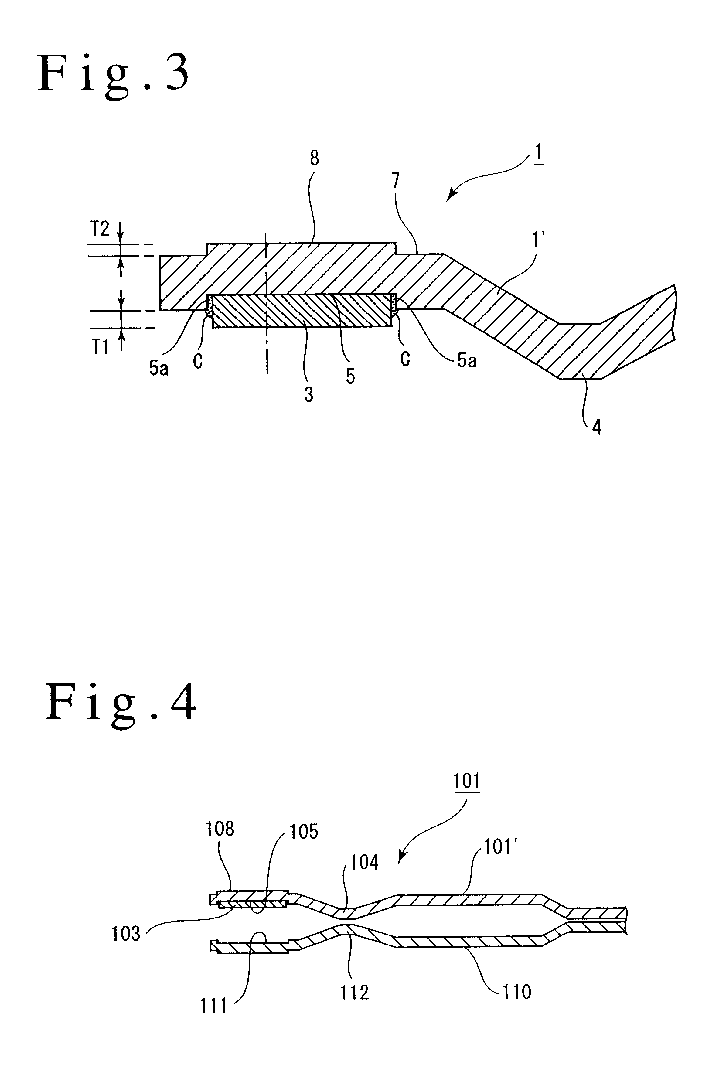
Thus, the combination of the upper plate 101' and the shim 103 comprises the same structure as provided by the first embodiment, and a lower plate 110 is constructed symmetrically in the vertical direction with respect to the upper plate 101' except that the lower plate 110 is not provided with a shim.

The shim 103 is intermittently welded to the plate 101' in the similar manner as in the first embodiment, and a coating C fills the clearance between the shim 103 and the annular groove 105 which accommodates it.

When the cylinder head gasket 101 is held sandwiched between the cylinder head and the cylinder block, the bead 104 of the upper plate 101' and the bead 112 of the lower plate 110 abut against each other to experience a compressive deformation (not shown), and the shim 103 on the upper plate 101' and an annular groove 111 formed in the lower plate 110 move toward each other, and the shim 103 is eventually received in the annular groove 111 to be abutted against the bottom of th...

third embodiment

A projecting step 313a which projects in the same direction as a shim 303 is formed around a combustion chamber opening formed in the inner plate 313. The projection height of the projecting step 313 is chosen to be equal to or slightly less than the projection height of the shim 303, whereby when the cylinder head gasket is held sandwiched between the cylinder head and the cylinder block, the shim 303 abuts against the projecting step 313a of the inner plate 313 which in turn abuts against a portion of the plate 310 which is located inward of the full bead 307. In other respects, the arrangement is similar to the

The fourth embodiment constructed in this manner is capable of achieving a similar functioning and effect as achieved by the third embodiment.

It should be understood that in the first to the fourth embodiments, the projection height of the shim may vary in the circumferential direction.

In the first to the fourth embodiments mentioned above, a full bead is used, but the inve...


PUM


Abstract

A cylinder head gasket comprises a plate, an annular groove formed to surround a combustion chamber opening formed in the plate, a metallic shim fitted into the annular groove, and a full bead located outward of the shim and projecting in the same direction as the shim. The shim is mounted on the plate by an intermittent welding.With this construction, the manufacturing cost can be reduced in comparison to the use of a conventional continuous welding or multi-layer welding. In addition, the thermal deformation of the shim and the plate itself is reduced as compared with when continuous welding or multi-layer welding is used, thus allowing the sealing capability to be improved. In addition, the cylinder head gasket is preferred for use in an engine of a higher combustion temperature than the combustion temperature when the shim is formed of a resinous material.

Description

The invention relates to a cylinder head gasket used in an engine, and more particularly, to an improvement in a cylinder head gasket having a shim which surrounds a combustion chamber opening.DESCRIPTION OF THE PRIOR ARTA cylinder head gasket is generally known in the art which is of the type having an annular metallic shim welded to a flat portion around a combustion chamber opening formed in a metal plate. A cylinder head gasket is also known in the art (see Japanese Laid-Open Patent Application No. 317,890 / 1997) which comprises an annular groove which surrounds a combustion chamber opening formed in a metal plate, an annular shim fitted into the annular groove, and an annular bead located outwardly of the shim and projecting in the same direction as the shim.Recently, as a higher efficiency is required of an engine, the engine combustion temperature has risen. With an increase in the combustion temperature, there is an increased temperature differential between cold and hot stat...

Claims


Application Information

Patent Timeline
Patent Type & Authority Patents(United States)
IPC IPC(8): F16J15/08F16J15/12F02F11/00
CPCF16J15/0818F16J15/0825F16J15/123F16J2015/0875F16J2015/0856F16J2015/0862F16J2015/085
Inventor JINNO, OSAMU
Owner TAIHO INDUSTRIES CO LTD
Learn More