Apparatus for automated finishing of interior surfaces

a technology of interior surface and automatic finishing, which is applied in cement mixing apparatus, mixing operation control, construction, etc., can solve the problems of insufficient acceptance of prior art designs by construction trade, time-consuming and labor-intensive process for finishing joints, and marginalization of air-pressurized systems

Inactive Publication Date: 2003-05-20
RENEGADE TOOL
View PDF39 Cites 26 Cited by
  • Summary
  • Abstract
  • Description
  • Claims
  • Application Information

AI Technical Summary

Problems solved by technology

The finishing of the joints is a time consuming and labor intensive process, since it is generally necessary to wait 24 hours between each application of mud in order to allow each layer to dry.
Unfortunately, most prior art designs have not been fully accepted by the construction trade.
In particular, air pressurized systems have been marginal at best as there is significant time lag during dispensing, and a potentially uneven application.
The application of drywall mud can also require large pieces of equipment including a mud tank that is hauled on trucks to the work site.

Method used


Image

  • Apparatus for automated finishing of interior surfaces
  • Apparatus for automated finishing of interior surfaces
  • Apparatus for automated finishing of interior surfaces

Examples


second embodiment

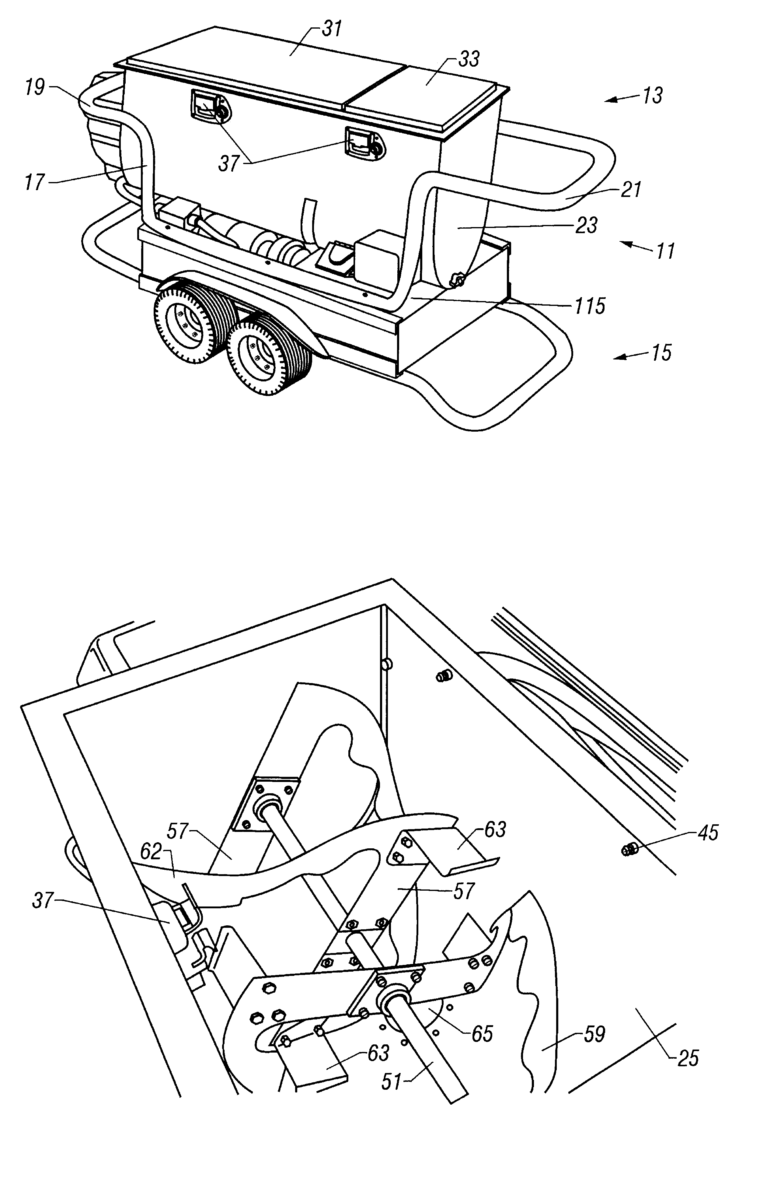
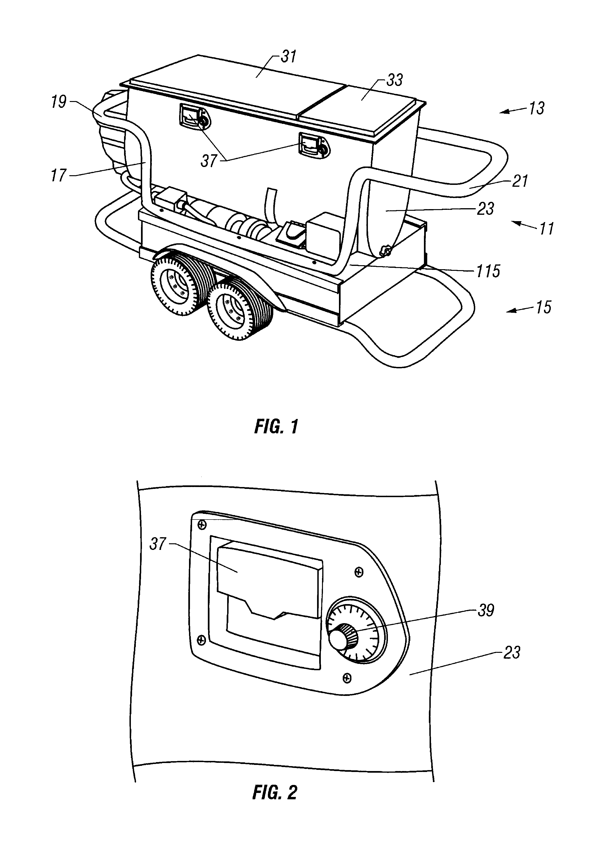
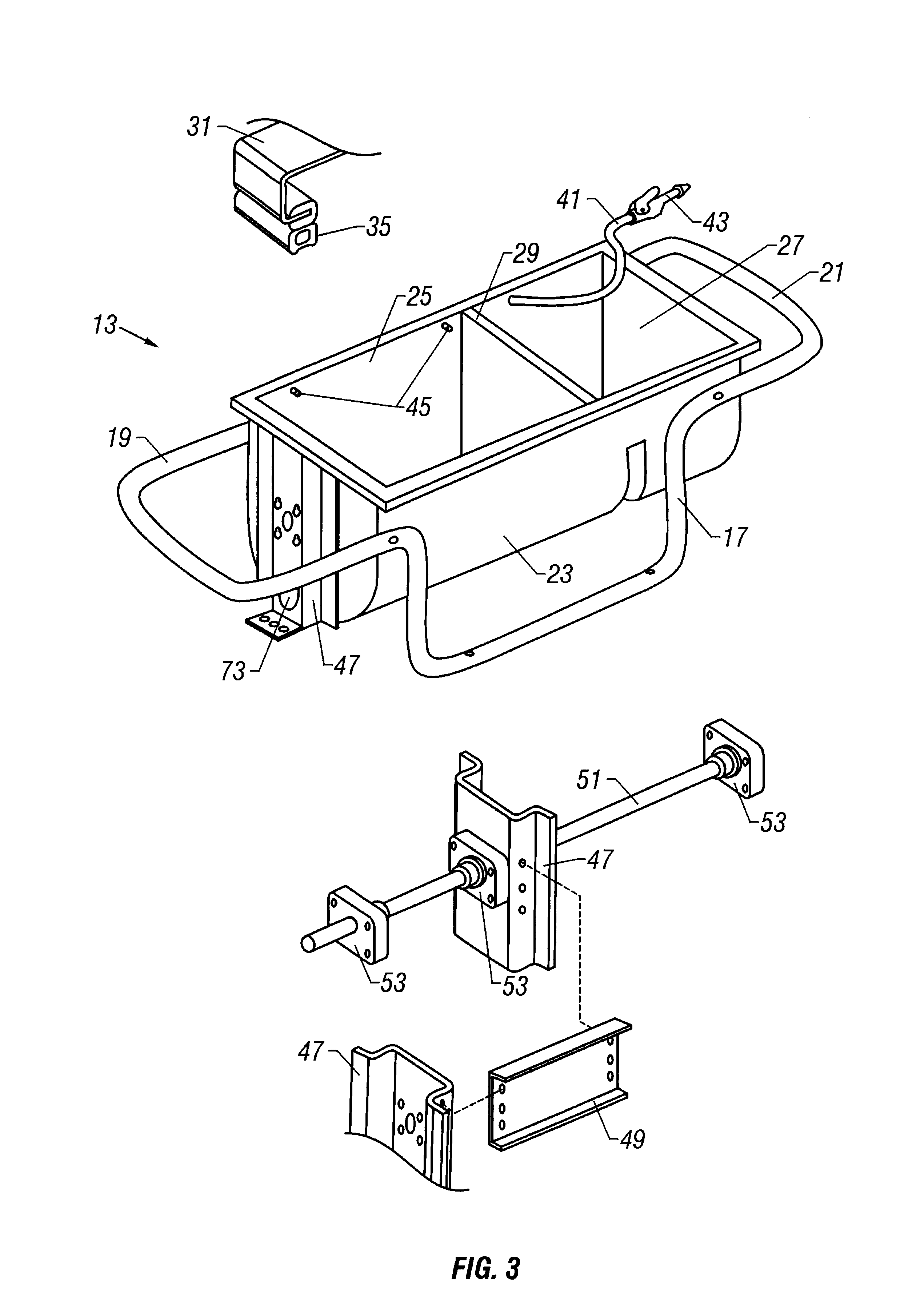
Referring now to FIGS. 19-21, an automated interior finish apparatus 165 is shown. The primary difference between apparatus 165 and apparatus 11 is that apparatus 165 has two pumping systems 167, 169 that dispense material from an enlarged mixing compartment 171. The dual pumps 167, 169 allow two operators to simultaneously use apparatus 165 with no loss in performance or efficiency over apparatus 11. Mixing compartment 171 is provided with two pump inlets 173, 175 (FIG. 21) to feed the two pumping systems 167, 169, each of which is aligned with force plates as described above. Apparatus 165 and apparatus 11 are otherwise operationally very similar or virtually identical. To facilitate better mobility for apparatus 165 around the job site, a small wheel assembly 177 is provided on one end of the lower portion of frame 179. Wheel assembly 177 may be pivotally relocated into or out of contact with the ground supporting surface.

third embodiment

Referring now to FIGS. 22-24, an automated interior finish apparatus 181 is shown. The primary difference between apparatus 181 and the previous two apparatus 11, 165 is that apparatus 181 is much smaller with only one compartment 183 for mixing, clean-up, and tool storage. Compartment 183 feeds a single pump and is much smaller and lighter than the previous versions of the invention. The lid 185 for compartment 183 has interior tool storage racks 187 (FIG. 23) that compensate for the lack of a separate storage compartment. There are preferably two folding tool storage racks 187 as shown for supporting tools in compartment 183 when apparatus 181 is not in operation. Because of its small size, apparatus 181 also has an external water tank 189 and hose rack 191 (FIG. 24) located on one side rather than beneath compartment 183.

Each of the aforementioned embodiments of the present invention is also capable of being partially disassembled or broken down into two separate, lighter pieces ...


PUM

PropertyMeasurementUnit
outer diameteraaaaaaaaaa
diameteraaaaaaaaaa
flexibleaaaaaaaaaa

Abstract

An automated interior finishing apparatus has an upper section for mixing material, and a lower section for conveying the material. The upper section has a mixing compartment and a separate washing / storage compartment. Each compartment has a hinged lid that forms an air-tight seal. The mixing compartment has a shaft with an auger for mixing compound with water. The lower section has a motor for driving a progressive cavity pump, which receives mixed material from the mixing compartment. The pump delivers a smooth and uniform supply of material through an external supply hose. The apparatus is used as one component of an overall automated interior finishing system and method for completing surface finishes. For example, one end of the supply hose is connected to the outlet end of the pump for delivering mixed material to a hand tool at the opposite end, such as a flat taper.

Description

1. Technical FieldThe present invention relates in general to improved interior surface finishing, and in particular to an automated apparatus for finishing interior surfaces such as drywall, acoustic, and painted surfaces.2. Description of the Prior ArtWallboard or drywall has become the dominant material in the production of interior building partitions. Interior building partitions typically comprise a studwall of vertical support members or studs that are spaced apart from each other in a parallel arrangement. The studs are used to support preformed panels or wallboards that are usually attached to the studwall with fasteners. A joint exists between adjacent ones of the the abutted wallboards.In order to provide a continuous flat surface appearance to the wall, it is necessary to apply a finish to the joint between the adjacent panels. Finishing typically requires the build-up of multiple layers of a mastic material or joint compound that is commonly referred to as mud. Mud is a...

Claims


Application Information

Patent Timeline
Patent Type & Authority Patents(United States)
IPC IPC(8): B28C9/00E04F21/08E04F21/10E04F21/02
CPCB28C9/004E04F21/165E04F21/10E04F21/08E04F21/026E04F21/1657
Inventor DILLINGER, DANIEL DEAO'MARA, JOHN ED
Owner RENEGADE TOOL
Why Eureka
Try Eureka