Modular three-dimensional optical switch

Inactive Publication Date: 2003-05-20
OMM +1
View PDF126 Cites 116 Cited by
  • Summary
  • Abstract
  • Description
  • Claims
  • Application Information

AI Technical Summary

Problems solved by technology

A disadvantage of 2D optical cross-connects (or switches) is that they are limited in the number of input and

Method used


Image

  • Modular three-dimensional optical switch
  • Modular three-dimensional optical switch
  • Modular three-dimensional optical switch

Examples


Embodiment Construction

The following description is not to be taken in a limiting sense, but is made for the purpose of describing one or more embodiments of the invention. The scope of the invention should be determined with reference to the claims.

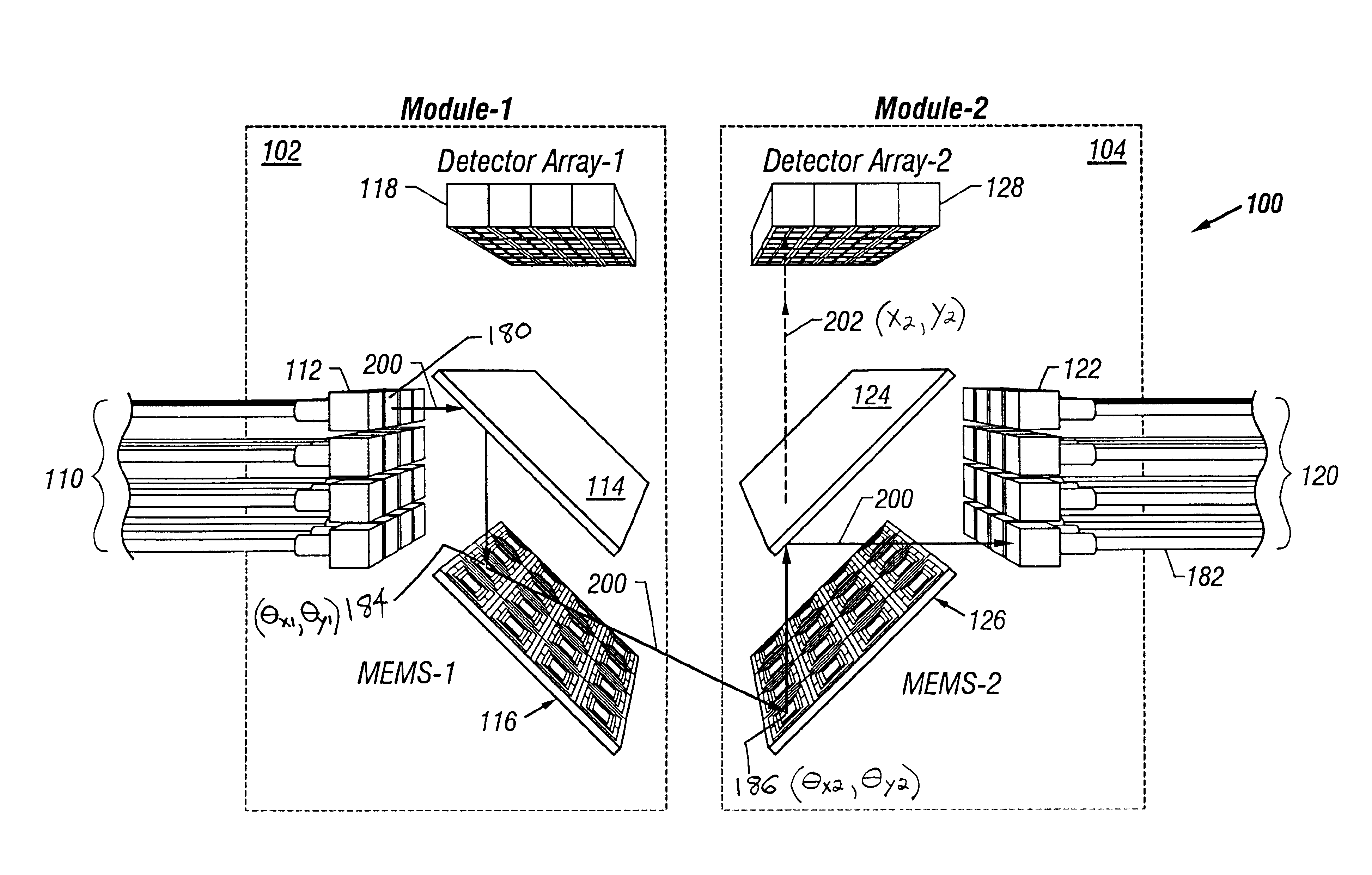
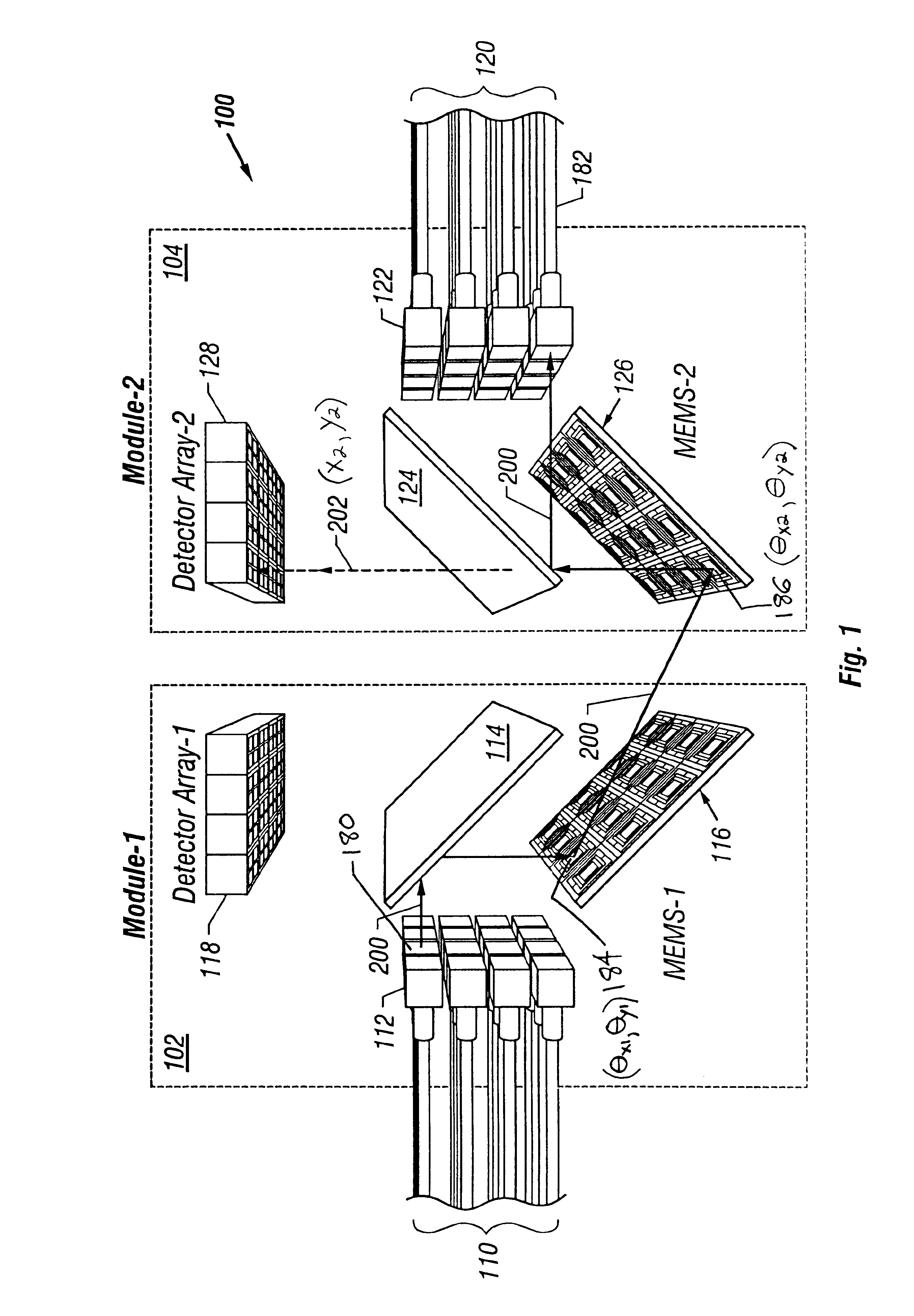
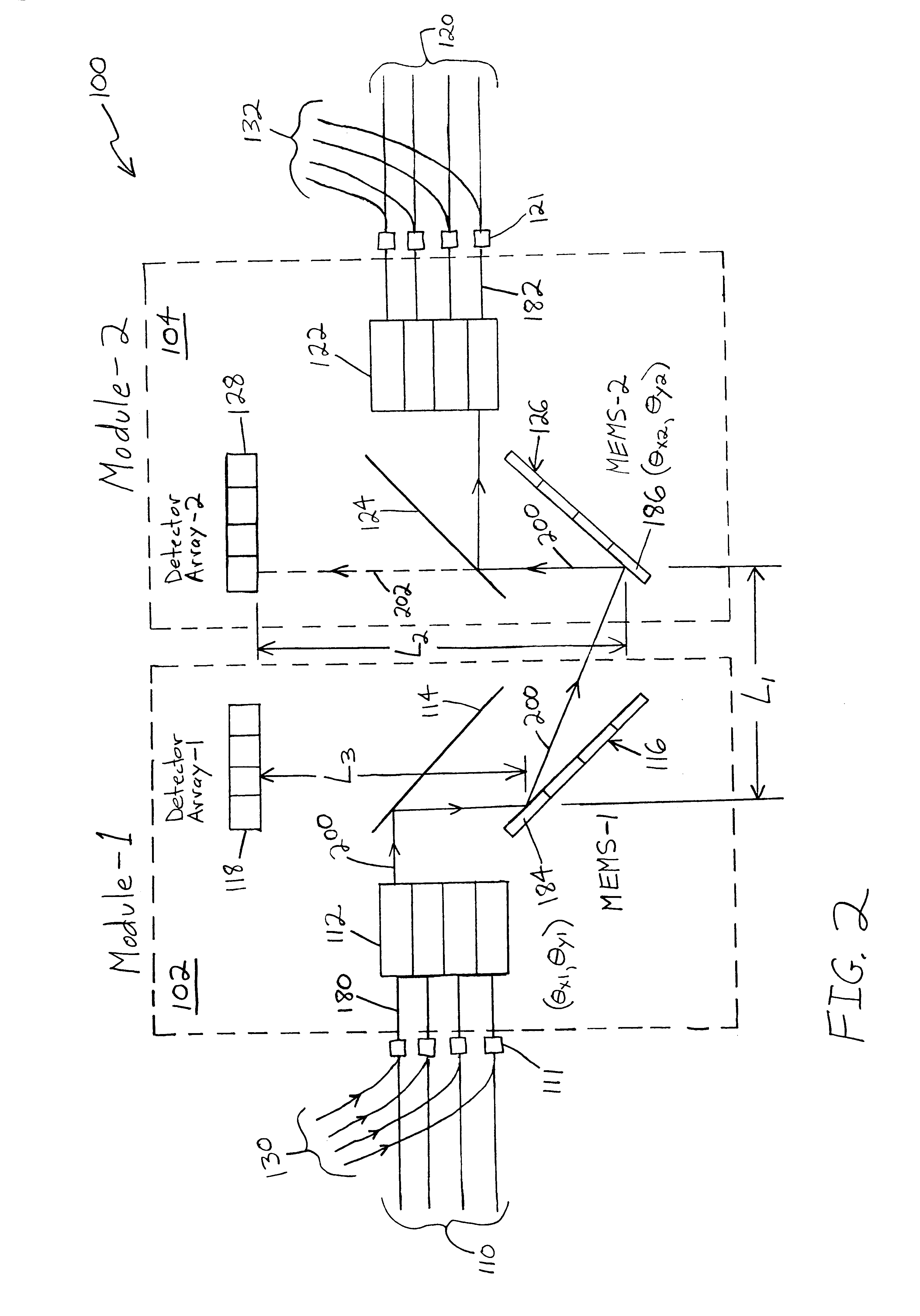
Referring to FIGS. 1 and 2, there is illustrated an optical switch 100 made in accordance with an embodiment of the present invention. The optical switch 100 is a three-dimensional (3D) optical switch that is capable of providing switchable cross connects between an array of input fibers and an array of output fibers. In other words, each of a plurality of single-wavelength optical input channels from the input fibers can be directed to a desired optical through channel of the output fibers.

Because the optical switch 100 (or optical cross-connect 100) is a 3D switch, there are multiple rows of input and output fibers that occupy multiple planes. In other words, the input and output fibers are not all arranged in the same plane as a common substrate. This allow...


PUM


Abstract

A modular three-dimensional (3D) optical switch that is scalable and that provides monitor and control of MEMS mirror arrays. A first switch module includes an array of input channels. Light beams received from the input channels are directed toward a first wavelength selective mirror. The light beams are reflected off of the first wavelength selective mirror and onto a first array of moveable micromirrors. The moveable micromirrors are adjusted so that the light beams reflect therefrom and enter a second switch module where they impinge upon a second array of moveable micromirrors. The light beams reflect off of the second array of moveable micromirrors and impinge upon a second wavelength selective mirror. The light beams reflect off of the second wavelength selective mirror and into an array of output channels. The alignment or misalignment of a data path through the switch is detected by directing two monitor beams through the data path, one in the forward direction and one in the reverse direction. The position of each of the monitor beams is detected after its reflection from the second moveable micromirror that it hits. The position data is used to determine the angles of the moveable micromirrors in the data path.

Description

1. Field of the InventionThe present invention relates generally to the field of optical switching. More specifically, the present invention relates to micro electro mechanical systems (MEMS) technology scanning mirrors for optical cross-connects and switches.2. Discussion of the Related ArtOptical switching plays an important role in telecommunication networks, optical instrumentation, and optical signal processing systems. Optical switches can be used to turn the light output of an optical fiber on or off, or, alternatively, to redirect the light to various different fibers, all under electronic control.Optical switches that provide switchable cross connects between an array of input fibers and an array of output fibers are often referred to as "optical cross-connects". Optical cross-connects are a fundamental building block in the development of an all-optical communications network. Specifically, in a fiber-optic communications network that uses electronic cross-connects, data t...

Claims


Application Information

Patent Timeline
IPC IPC(8): G02B6/35H04Q11/00
CPCH04Q11/0005G02B6/359H04Q2011/0024H04Q2011/003H04Q2011/0039H04Q2011/0083G02B6/3512G02B6/3556H04Q2011/0043
Inventor MAKRUGLICK, EZEKIEL JOHN JOSEPHREILEY, DANIEL J.MARCHAND, PHILIPPE JEANGLOECKNER, STEFFEN
Owner OMM
Why Eureka
Try Eureka