Process for cutting out panels or the like

a cutting and panel technology, applied in the direction of lamination, automatic control devices, feeding apparatuses, etc., can solve the problems of uneven distribution of decorative layers, uneven decoration on individual panels, gaps, etc., and reduce the quality of the laid-out floor

Inactive Publication Date: 2003-05-27
KRONOTEC
View PDF20 Cites 41 Cited by
  • Summary
  • Abstract
  • Description
  • Claims
  • Application Information

AI Technical Summary

Benefits of technology

With this process, it is possible to automatically record or determine the paper growth and, with the resulting data, to adjust the saw and to position the wood board in front of the saw, without the need for conceptual activity, which is fundamentally subject to risk of error. Since a reproducible adjustment is made again and again, the quality of the sawed panels is very high. Even difficult decorations, e.g., file decorations, can be processed with a high level of quality and in a cost-effective way.
If another defined point is recorded with a third camera and the actual position of the points is again compared with the desired position of the points, the growth in the other direction can simultaneously be determined. In keeping with the determined data, both the longitudinal saw and the transverse saw are adjusted, and the wood board is moved in one direction by half the amount of the offset from the saw; here the offset, i.e., the growth in length and width, do not have to be identical, and the overall result is that even a complicated behavior can be controlled. Instead of identifying defined points in the decorative layer with the camera, it is also possible to apply markings to the edge of the paper web, markings which can be detected by the cameras. With this measure it is possible to apply the process according to the invention even when a low-contrast decoration is involved.
With this measure it is possible to individually adjust the tolerance to the given decoration, which permits production to be immediately adjusted to the demanded or accepted standard of quality. Thus, in a tile decoration it will be necessary to select a fundamentally smaller tolerance range than is the case with a grooved floor decoration or a veneer decoration. The saw blades can be positioned on a common shaft. It is also possible to form the saw from individually driven saw blades, whose distance from each other is adjustable.

Problems solved by technology

If this decorative board is only to be cut into individual panels, the growth in length and width must be taken into account, since otherwise there will be a non-uniform distribution of the decoration on the individual panels.
The result of this would be that the floor composed of an unevenly distributed decorative layer would exhibit gaps in the decoration on the connecting rims of the panels.
Even if these gaps amount to only a few millimeters, they are noticeable upon closer observation, and this has a negative aesthetic effect and thus diminishes the quality of the laid-out floor.
Since this occurs manually, the process is very time-consuming and therefore cost-intensive.
If the dimensions are not correctly determined, the danger of immediately producing rejects is high.
A discrepancy of only 2 mm is unacceptable since this could entail the complete displacement of the joint.
Thus the saw must be permanently reset, which highly increases the cost of the panels.
With this process, it is possible to automatically record or determine the paper growth and, with the resulting data, to adjust the saw and to position the wood board in front of the saw, without the need for conceptual activity, which is fundamentally subject to risk of error.

Method used


Image

  • Process for cutting out panels or the like
  • Process for cutting out panels or the like
  • Process for cutting out panels or the like

Examples


Embodiment Construction

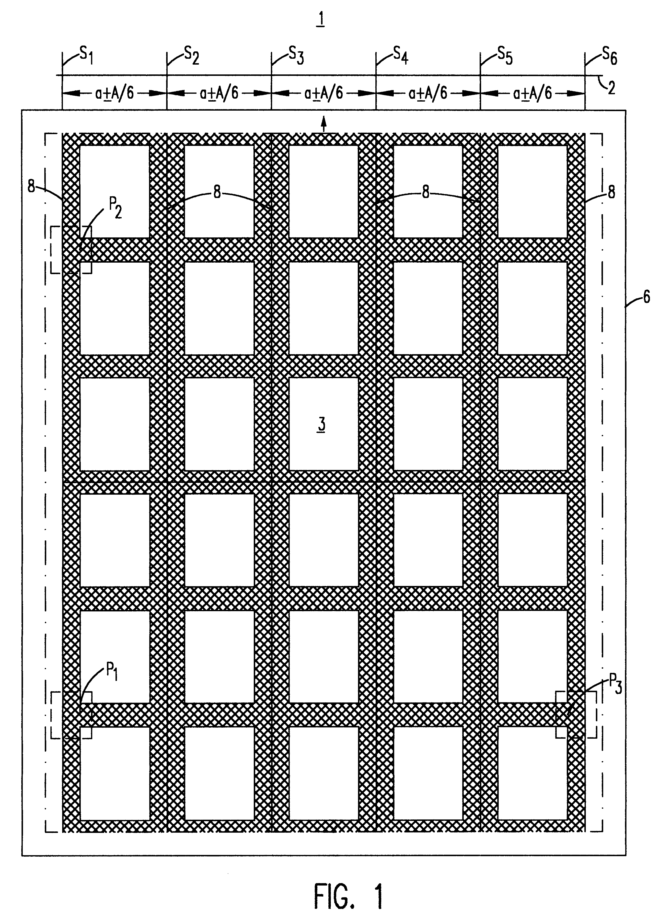
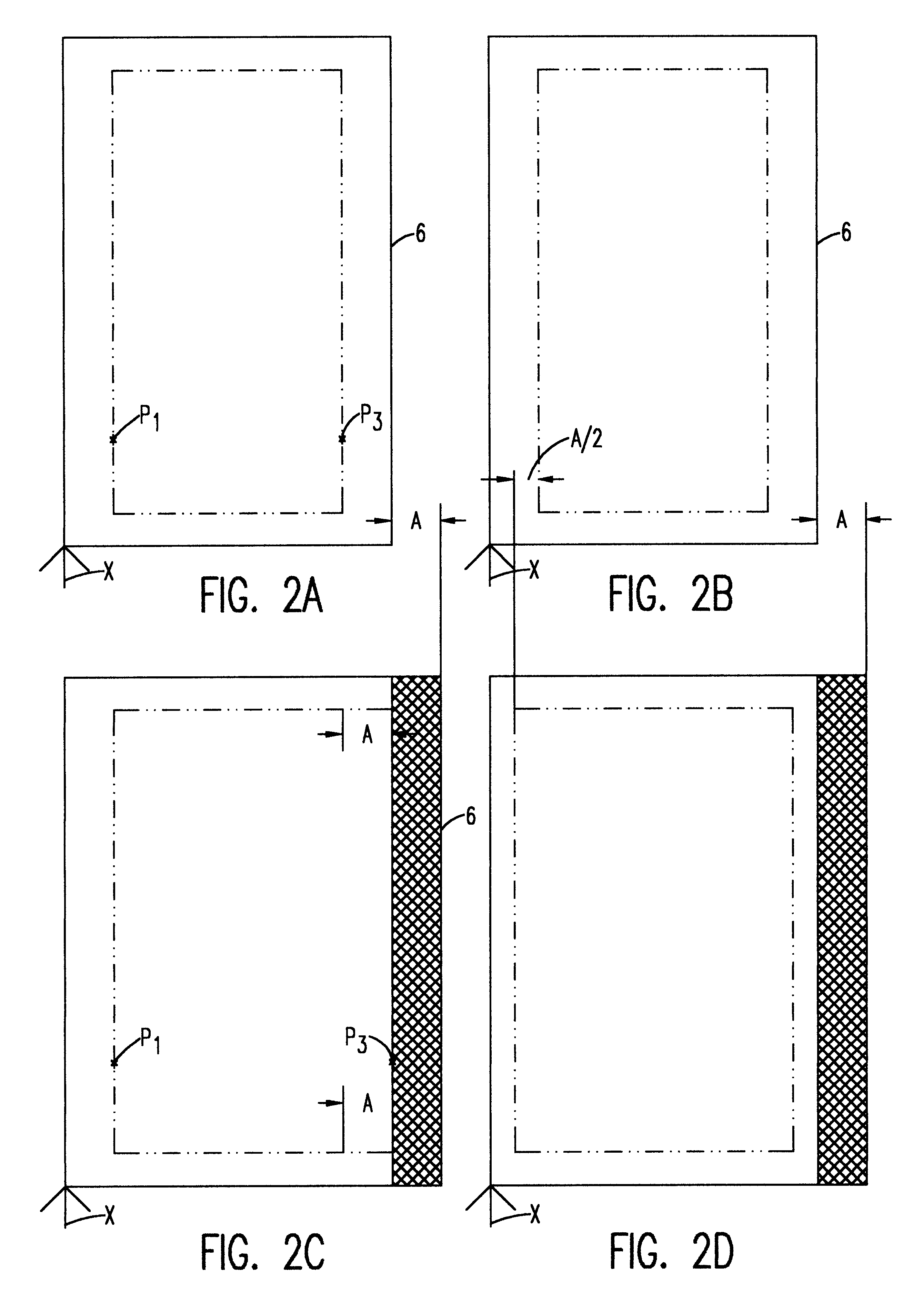
FIG. 3 shows a board-dividing apparatus that is provided with a roller path 5, onto which the wood fiber panel 6 furnished with a decorative layer 3 can be laid. The board-dividing apparatus is provided with a saw 1 that consists of a plurality of saw blades S.sub.1, S.sub.2, S.sub.3, S.sub.4, S.sub.5, S.sub.6, that are positioned in parallel fashion. The saw blades S.sub.n are spaced at a distance of a. They can be positioned individually or on a common shaft 2. With the saw 1 depicted here the wood fiber panel 6 could be divided in the longitudinal direction. To divide the wood fiber panel 6 in the transverse direction, a transverse saw (not shown here) would be positioned with a 90.degree. shift. After a wood fiber panel 6 is divided in the longitudinal and transverse direction, the individual panels are fed to a milling device for profiling, which is not shown here in greater detail.

Three cameras 4a, 4b, 4c are positioned in front of the saw and above the roller path. Defined po...


PUM

PropertyMeasurementUnit
displacementaaaaaaaaaa
lengthaaaaaaaaaa
widthaaaaaaaaaa

Abstract

A wood fiber board (6) which is provided with a decorative layer (3) of paper or similar material, and where the length or width value of the decorative layer (3) deviates from its original value after it is applied to the wood fiber board (6), is cut into uniform panels using a board-dividing apparatus that compensates for these deviations. The board-dividing apparatus has a saw (1) that preferably has a plurality of saw blades (S1, S2, . . . Sn) which are adjustably spaced in parallel fashion. The board-dividing apparatus is equipped with a number of cameras and with controller which utilizes deviation measurement information to adjust the spacing of the saw blades. The wood fiber board (6) is first aligned with at least one initial camera (4a) at a point P1. Then, predetermined points (P1 and P2) in the decorative layer (3) are recorded by the first camera (4a) and a second camera (4b). A distance (L) between the points (P1 and P2) is determined, and thee discrepancy in the width or length value is determined by comparison of the actual position and the desired position of the points (P1 and P2). Then, the value of the determined discrepancy (A) is placed in relation to the number (n) of the saw blades (Sn), and the parallel spacing (a) of the saw blades (Sn) is modified by the value of the ratio of the discrepancy to the number of saw blades (A / n). The orientation of the wood fiber board (6) to the saw (1) is displaced to one side in the amount of one half the determined discrepancy (A), and then the wood fiber board (6) is transported toward the saw (1) for cutting out the panels.

Description

1. Field of the InventionThe invention is directed to a process for cutting panels, or the like, from a wood fiber board which is provided, in particular, with a decorative layer basically consisting of paper, where the length and / or width value of the decorative layer deviates from its original value after it is applied to the wood fiber board, which process employs a board-dividing apparatus exhibiting at least one saw, where the saw is formed by a plurality of saw blades which are adjustably spaced in parallel fashion.2. Background DescriptionPanels are employed in, e.g., flooring, particularly laminate flooring. The desired decoration (parquet, wood graining, floor tiles, etc.) is printed on a paper web, which is then coated with artificial resin and rolled onto a roller. The decorative web thus prepared is then applied to the wood fiber boards at the floor manufacturer. With the printing of the decoration onto the paper web, the later sealing of the paper web with artificial re...

Claims


Application Information

Patent Timeline
Patent Type & Authority Patents(United States)
IPC IPC(8): B27B5/00B27B31/06B27B5/06B27B31/00
CPCB27B5/06B27B31/06Y10T156/1067Y10T156/13Y10T156/1074Y10T156/1052Y10T428/167Y10T83/531Y10T83/0495Y10T83/525Y10T83/04Y10T83/6584Y10T83/05Y10T83/145Y10T83/543Y10T83/533
Inventor TYCHSEN, DETLEF
Owner KRONOTEC
Why Eureka
Try Eureka