Process for improving material thickness distribution within a molded bottle and bottle therefrom

a technology of molded bottles and bottles, which is applied in the direction of transportation and packaging, rigid containers, other domestic articles, etc., can solve the problems of difficult blow molding, uneven distribution of material thickness, and difficulty in blow molding

Inactive Publication Date: 2003-05-27
AMCOR RIGID PLASICS USA LLC
View PDF5 Cites 18 Cited by
  • Summary
  • Abstract
  • Description
  • Claims
  • Application Information

AI Technical Summary

Problems solved by technology

While the technician strives for the uniform material thickness distribution in the molded bottle, compromises are still often necessary.
Bottles with generally rectangular or oval cross-sectional shapes, shapes with its inherent major or primary axis and minor or secondary axis generally perpendicular to the bottle longitudinal axis, are often difficult to blow-mold when made with the injection-molded preform.
Consequently, material thickness distribution is not uniform.
While this approach, sometimes known as "heat profiling," is effective for improving material thickness distribution uniformity within the sidewall, it is generally not effective for improving material thickness distribution uniformity within the push-up and the molded bottle base or bottom portion.
While it is feasible to heat profile the entire closed-end to a specific temperature, it is not practical, because of its small size, to heat profile sub regions within the closed-end.
Second, the wall thickness in an area of the push-up surrounding the longitudinal axis of the molded bottle remains relatively thick because the preform closed-end region of the inflating preform has little opportunity to stretch or thin before contacting the relatively cool cavity surface of the blow-mold tool forming the bottle configuration.
Consequently, the lack of effective heat profiling and the lack of sufficient stretch or thinning of the preform with its circular cross-sectional shape causes the material distribution surrounding the longitudinal axis of the bottle push-up and bottom to have a predominantly thick circular character.
Consequently, the material within these thick areas is prone to warp and distort.
Furthermore, molding technicians, attempting to increase production output, will often remove the bottle from the blow-mold tool before thick areas have sufficiently cooled risking additional distortion of those areas.
However, the distortions can create significant problems with bottles having the generally non-circular cross-sectional configuration because the distortions can often extend into the base or bottom contact surface.
At best, this creates a minor aesthetic problem.
At worst, this can alter bottle standing stability by creating a condition molding technicians refer to as a "rocker bottom."
The rocker bottom condition can create a bottle stability problem on high-speed filling lines, particularly before the bottle filling station.
This reduces productivity and increases molding cost.
Rib-like projections that are too high or too sharp will tend to overcompensate and to over-thin material thickness.

Method used


Image

  • Process for improving material thickness distribution within a molded bottle and bottle therefrom
  • Process for improving material thickness distribution within a molded bottle and bottle therefrom
  • Process for improving material thickness distribution within a molded bottle and bottle therefrom

Examples


Embodiment Construction

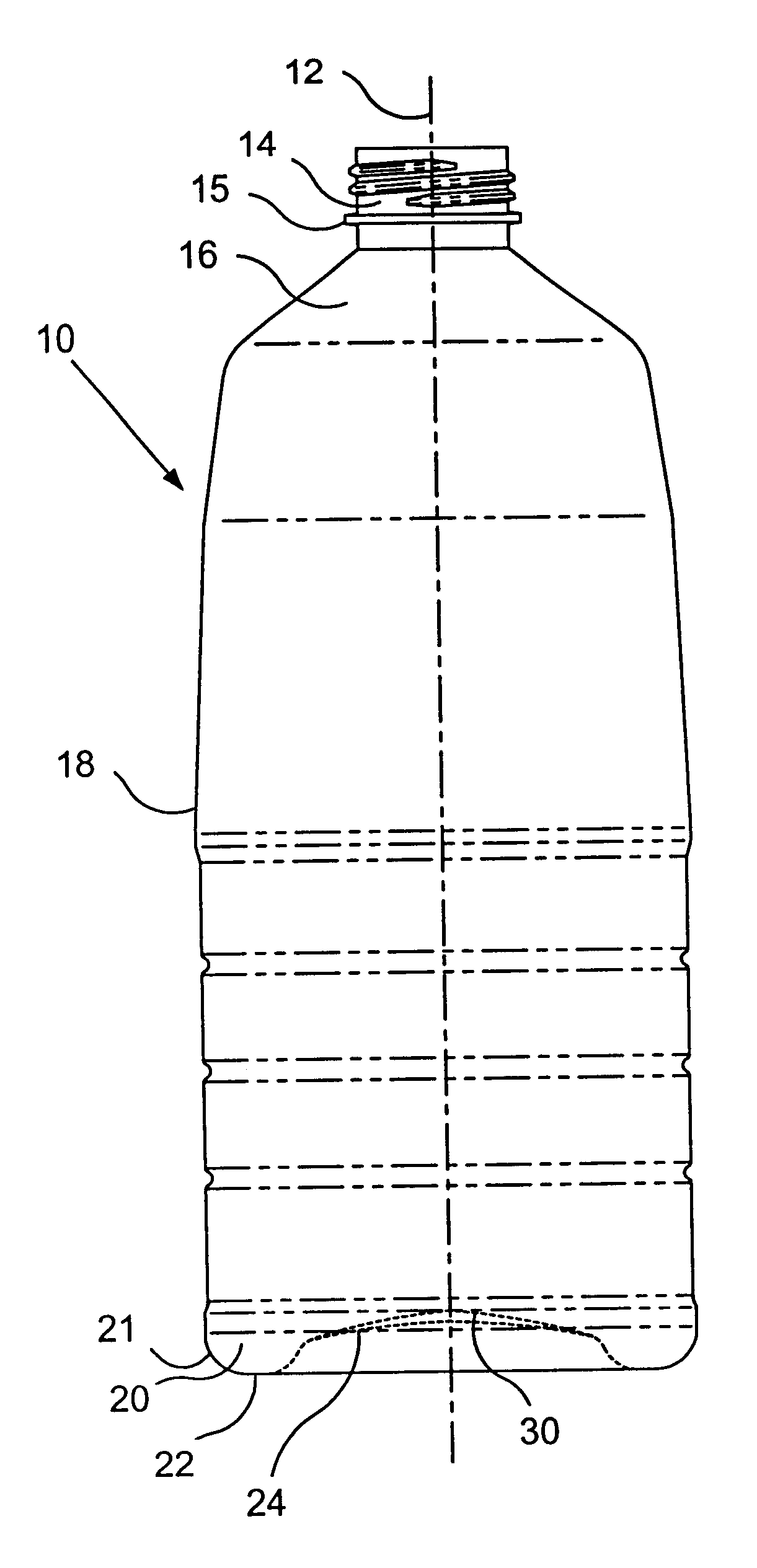
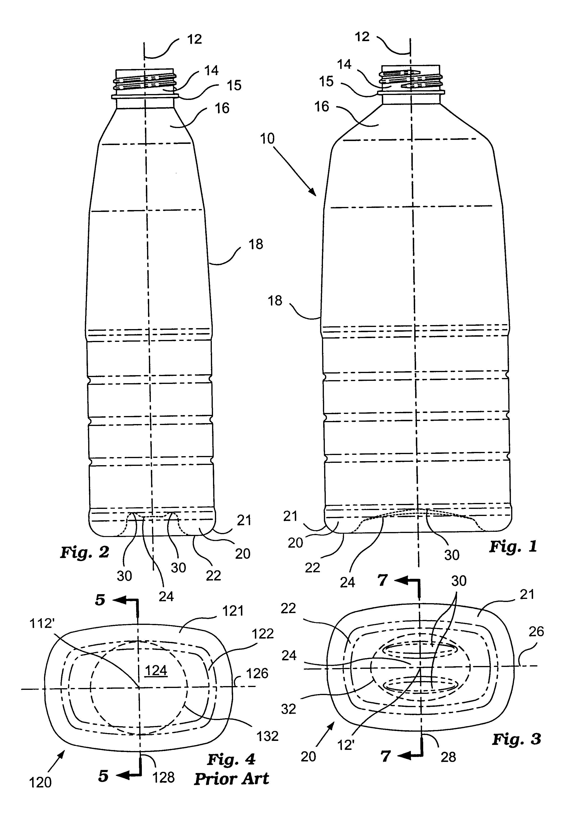
Referring now to the drawings, FIG. 1 and FIG. 2 illustrate a bottle 10 that is typical of this invention. Proper practice of the manufacturing process creates certain desirable readily identifiable characteristics in the molded bottle 10. The process and the bottle created by the process are specifically related. Understanding the process requires understanding bottle 10 attributes that result from the process.

Bottle 10 has a longitudinal axis 12, neck finish 14 surrounding an open-end, flange 15, shoulder 16, sidewall 18, and base or bottom 20. Neck finish 14, flange 15, shoulder 16, sidewall 18, and bottom 20 combine to define an outer surface shape to bottle 10.

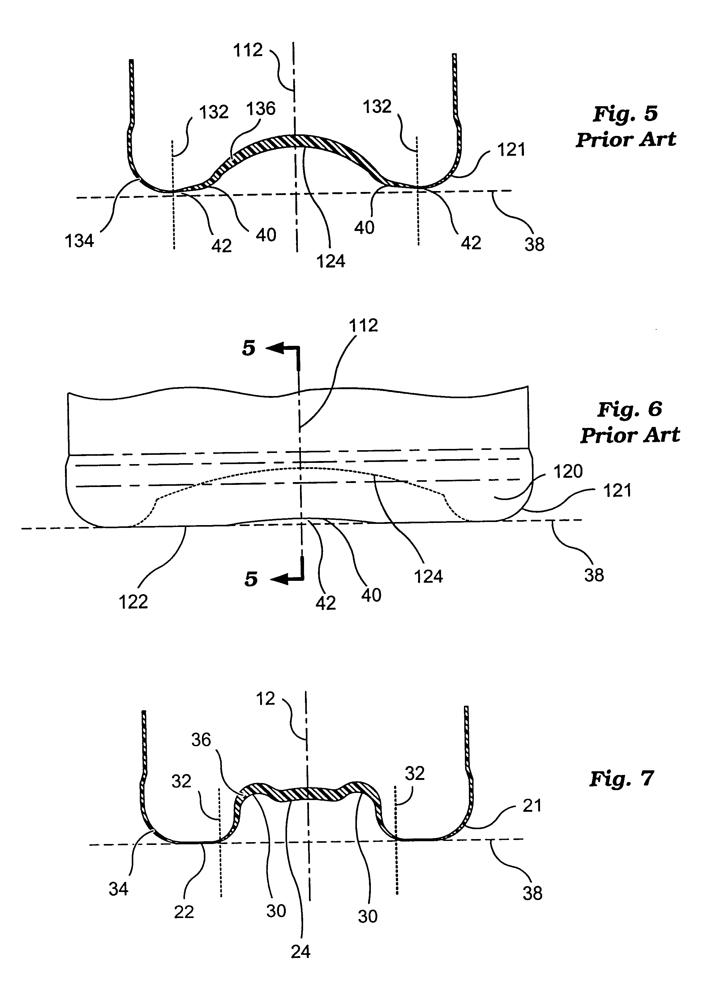
Bottom 20 consists of a contact surface 22, which contacts a resting surface 38 (FIG. 7) when bottle 10 is standing in a normal upright fashion. Bottom 20 also consists of a chime 21 and a push-up 24 that merges with and generally rises above contact surface 22. The chime 21 is an outside curved portion or outer edge port...


PUM

PropertyMeasurementUnit
thickness distributionaaaaaaaaaa
pressureaaaaaaaaaa
shapeaaaaaaaaaa

Abstract

A process and a bottle made from this process where the bottle has improved material thickness distribution within the bottom or base portion. The bottle has a noncircular cross-sectional configuration with corresponding major and minor axes. The mold-base region of the bottle mold-cavity features at least one standing rib-like projection generally parallel to the major axis. The standing rib-like projection increases surface distance in a direction generally corresponding with the minor axis. An expanding heated preform traverses the increased surface distance causing the preform to thin more than what otherwise would be the case thus improving material thickness distribution of the base portion that in turn minimizes unwanted bottle shape distortions.

Description

1. Field of the InventionThis invention relates to a process for improving material thickness distribution within a molded bottle and the bottle made with the process. The bottle has a closed base or bottom, an open-end, a longitudinal axis, and a generally square, generally rectangular, or generally oval or other noncircular cross-sectional shape typically perpendicular to the longitudinal axis. In particular, the process is for improving material thickness distribution within the bottle base portion or bottom. The bottle base portion contains a chime, contact surface, and push-up region.The process relies on a mold-cavity base or bottom region of a blow-molding tool modified with at least one generally straight standing rib. The rib (or two or more parallel ribs) alters mold-cavity bottom geometry that redirects material flow during bottle manufacture allowing better placement and distribution of material that in turn minimize unwanted shape distortions in the molded bottle that c...

Claims


Application Information

Patent Timeline
Patent Type & Authority Patents(United States)
IPC IPC(8): B29C49/48B65D1/02B29C49/54B29C49/08B29C49/06B65D8/12
CPCB65D1/0276B29C49/48B29C49/06B29C49/08B29C49/541B29L2031/7158B29C2949/0715
Inventor WURSTER, MICHAEL P.GAYDOSH, KEVIN D.LABOMBARBE, CHRISTOPHER C.
Owner AMCOR RIGID PLASICS USA LLC
Why Eureka
Try Eureka