

Supporting body for a shower tub
a technology for shower tubs and supports, applied in bathroom accessories, domestic applications, applications, etc., can solve the problems of gutters and dirt carrying, floor tiles resting on hollows, prone to breakage, etc., and achieve the effect of convenient mounting and disassembly
- Summary
- Abstract
- Description
- Claims
- Application Information
AI Technical Summary
Benefits of technology
Problems solved by technology
Method used
Image

Examples
Embodiment Construction
)
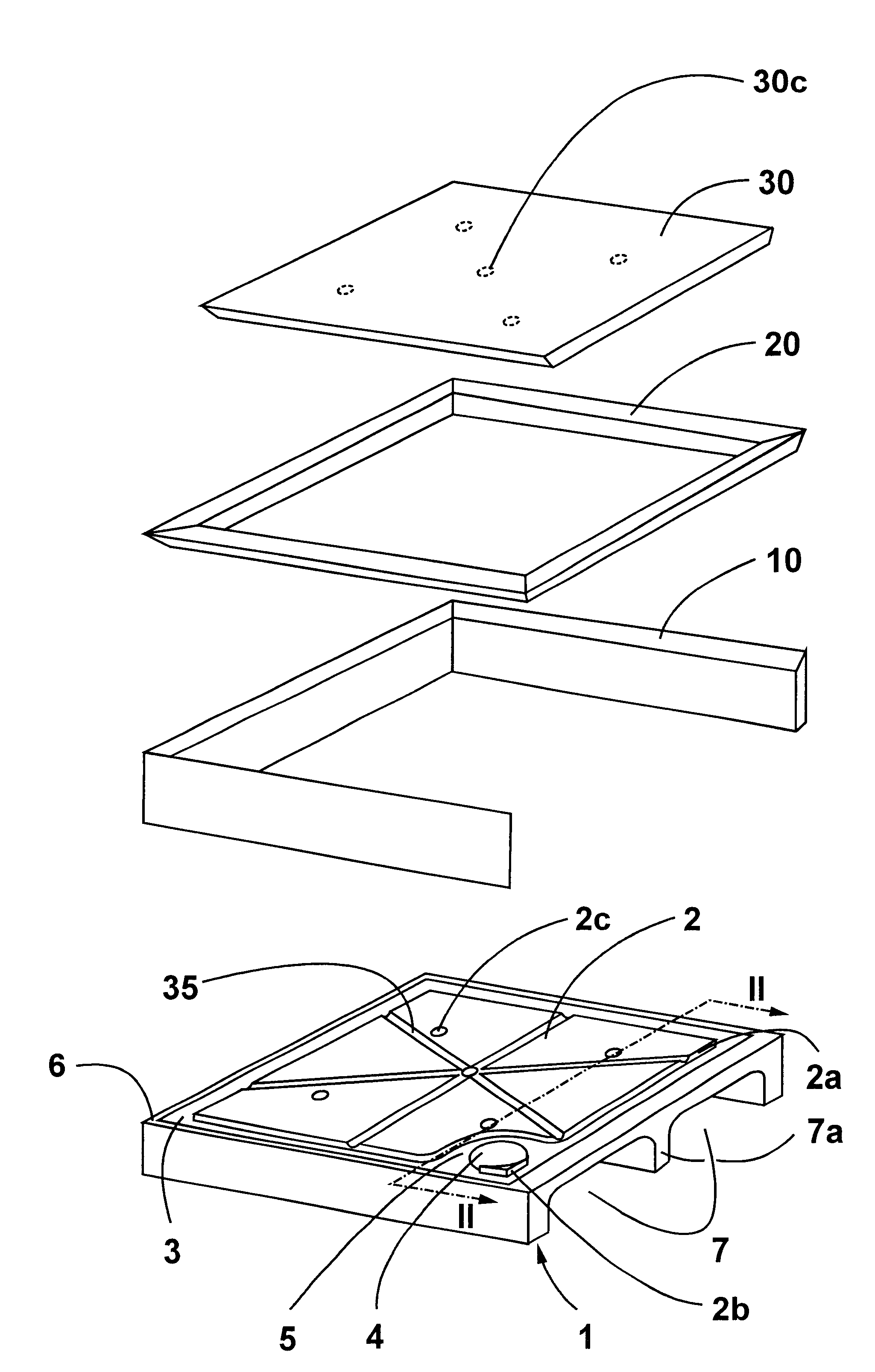
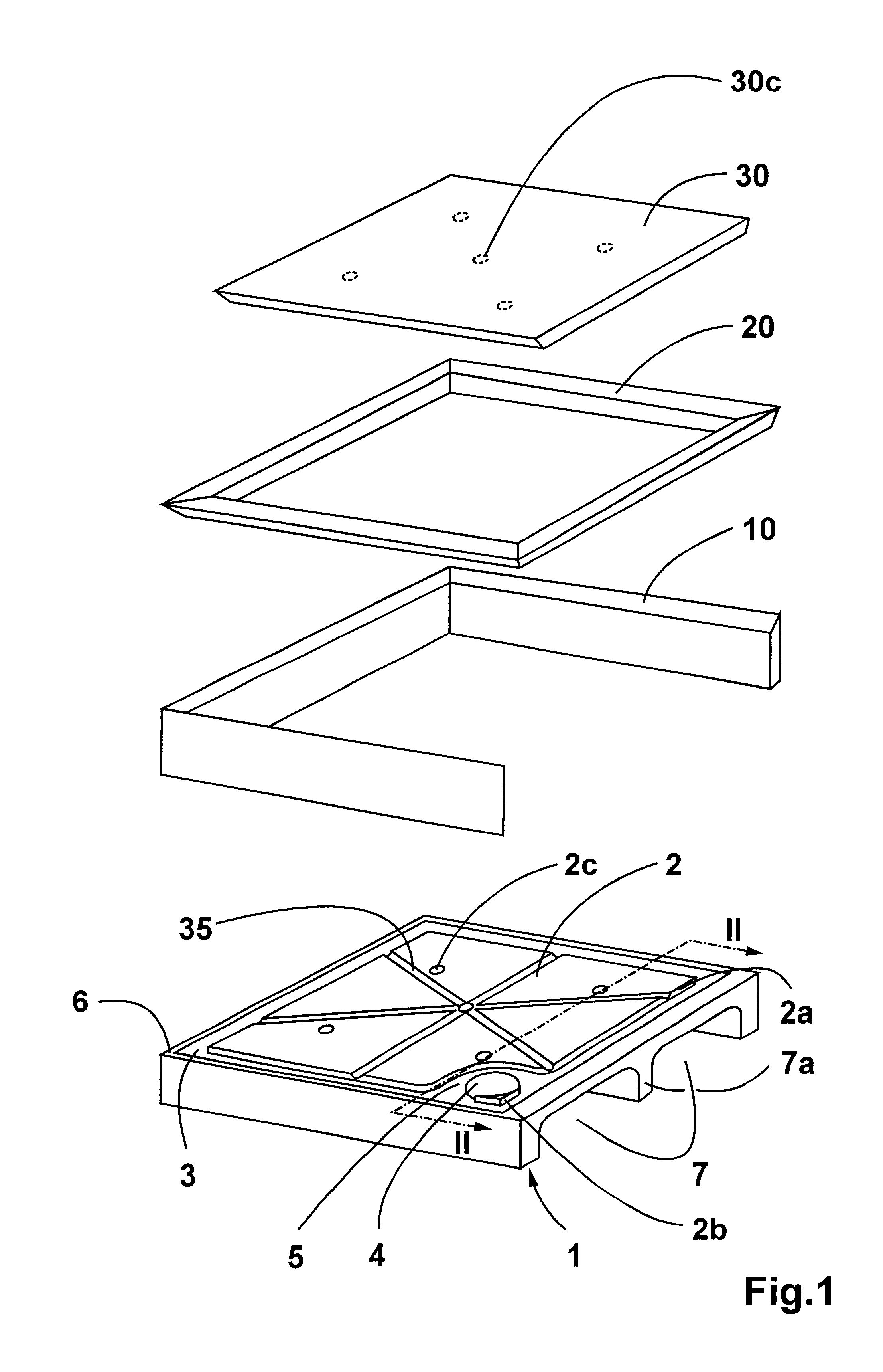
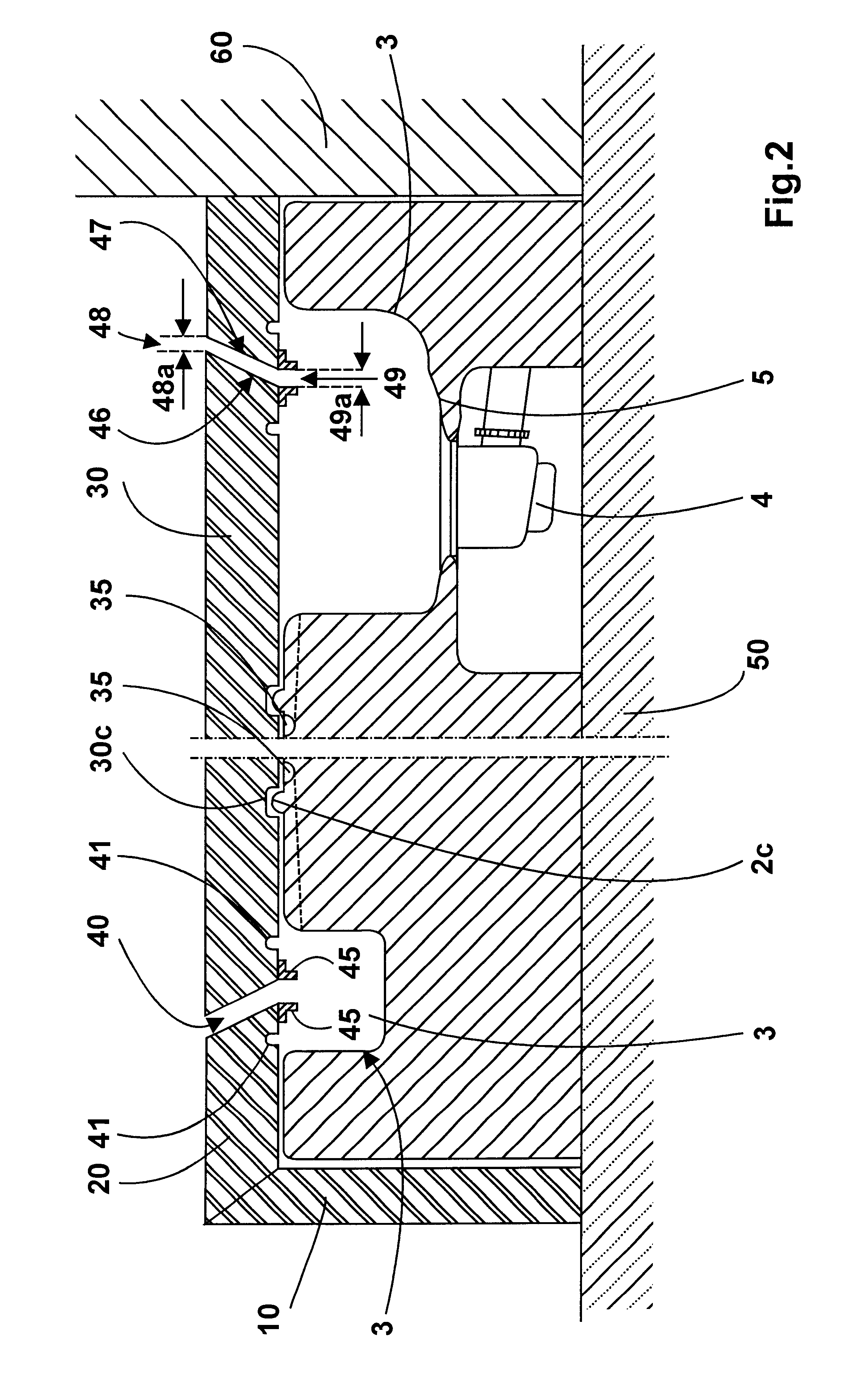
The structure of an overall shower tub with or on the supporting body 1 respectively can be surveyed--as already mentioned--from FIG. 1. The supporting body 1 rests on or in the lime floor 50 and abuts the wall 60. FIG. 1 shows the supporting body indicated at 1 whose margin 6 is covered by a margin border 10, wherein a margin frame 20 can be placed onto the margin border 10, the margin frame 20 framing the floor tile 30 resting on the landing 2 of the supporting body 1. Accordingly, the shower tub itself is substantially mounted onto the supporting body or onto the margin thereof respectively. An annular channel 3, which is inclined toward the drain 4, surrounds the landing 2. The drain 4 is provided with a marginal region 5 that is stepped downward with respect to the landing 2, said marginal region forming around the drain an annular area that serves to receive sealing means such as O rings for example. Accordingly, the supporting body is inasmuch a component part of the shower ...
PUM
 Abstract
Description
Claims
Application Information