Pneumatic tire having tread including pairs of sipes

a pneumatic tire and tread technology, applied in the field of pneumatic tires, can solve the problems of difficult to obtain suitable properties for both braking and traction, insufficient controllability at small steering angles, and ineffective method of forming sipes, etc., to achieve the effect of improving braking and traction properties, reducing friction, and reducing friction

Inactive Publication Date: 2003-06-03
BRIDGESTONE CORP
View PDF22 Cites 67 Cited by
  • Summary
  • Abstract
  • Description
  • Claims
  • Application Information

AI Technical Summary

Benefits of technology

In the above pneumatic tire, it is preferable that the angle between the first portion of the first side wall and the radial direction of the tire and the angle between the second portion of the second side wall and the radial direction of the tire are each +5 to +15.degree.. When force is applied from the direction of the apex of the chevron, sufficient rigidity is obtained and falling down (collapse) of the block can be suppressed.
In the above pneumatic tire, it is preferable that an angle formed by the radial direction of the tire and the first side wall at the second tire circumferential direction end of the block pair and an angle formed by the radial direction of the tire and the second side wall at the second tire circumfe

Problems solved by technology

This means that the conventional method of forming sipes is not effective for improving cornering property, although the method is effective for improving braking and traction properties on ice.
Therefore, controllability at small steering angles is often insufficient.
Even if the angle of sipes with respect to tire circumferential direction is changed, it is difficult to obtain suitable properties for both of braking and traction because rigidity of the block with respect to the forward force is different from that with respect to the backward force.
However, when the density of the sipes in an entire block is incr

Method used


Image

  • Pneumatic tire having tread including pairs of sipes
  • Pneumatic tire having tread including pairs of sipes
  • Pneumatic tire having tread including pairs of sipes

Examples


first embodiment

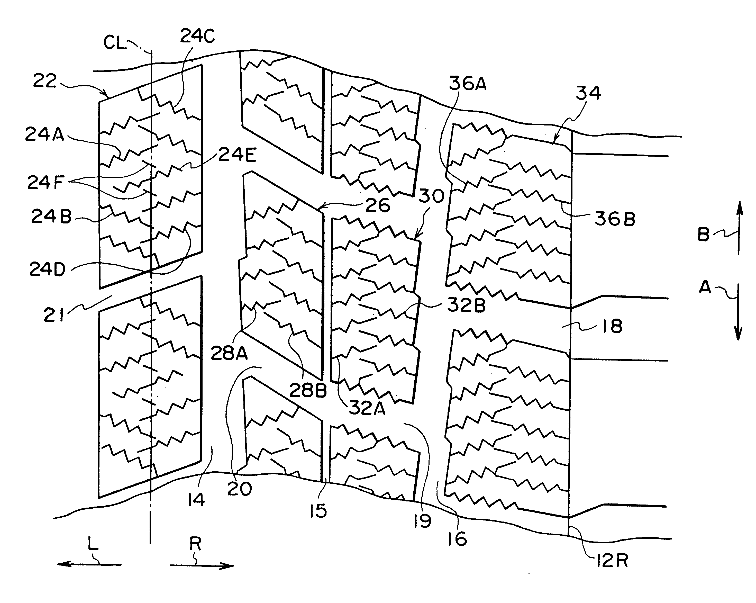
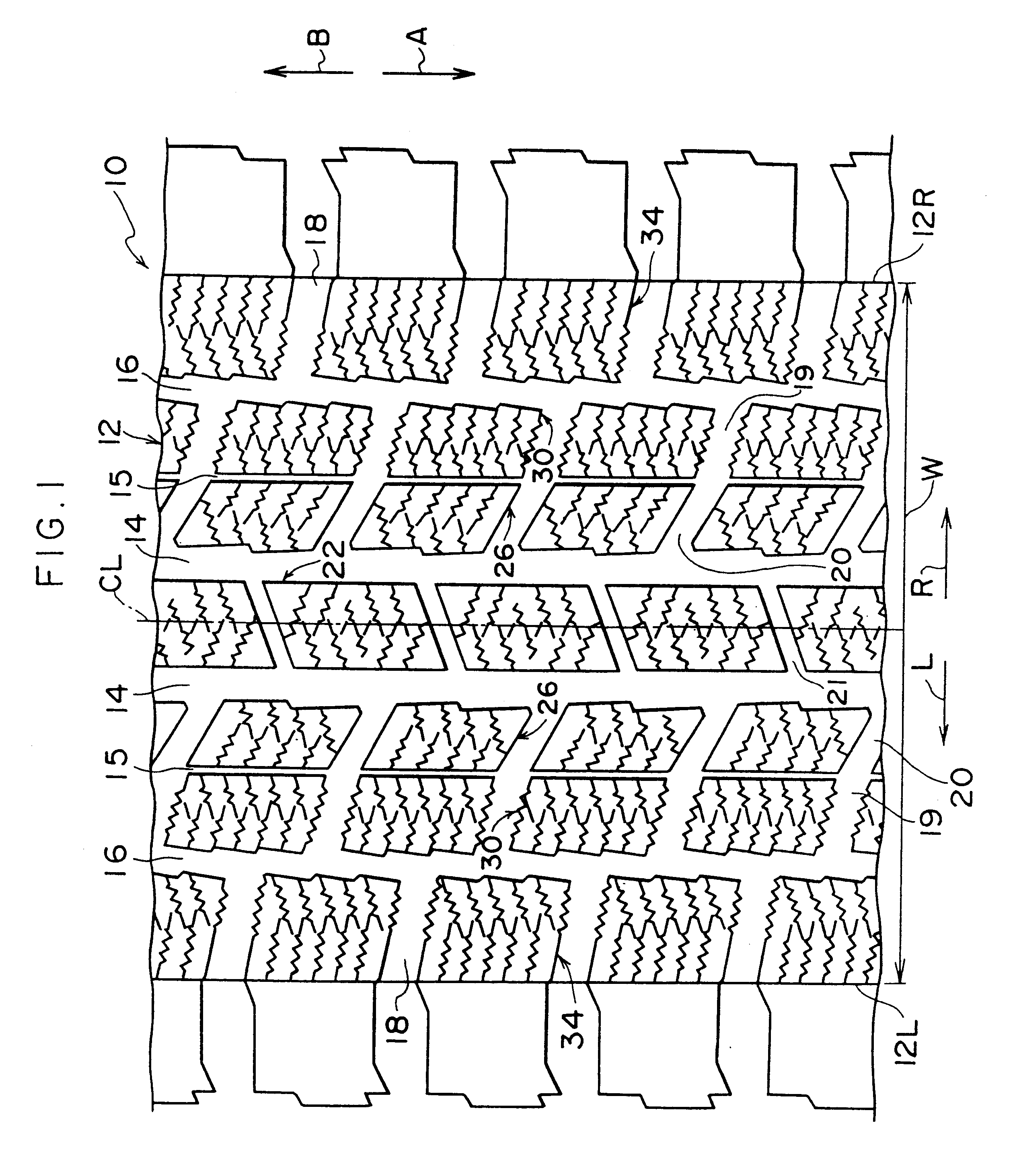
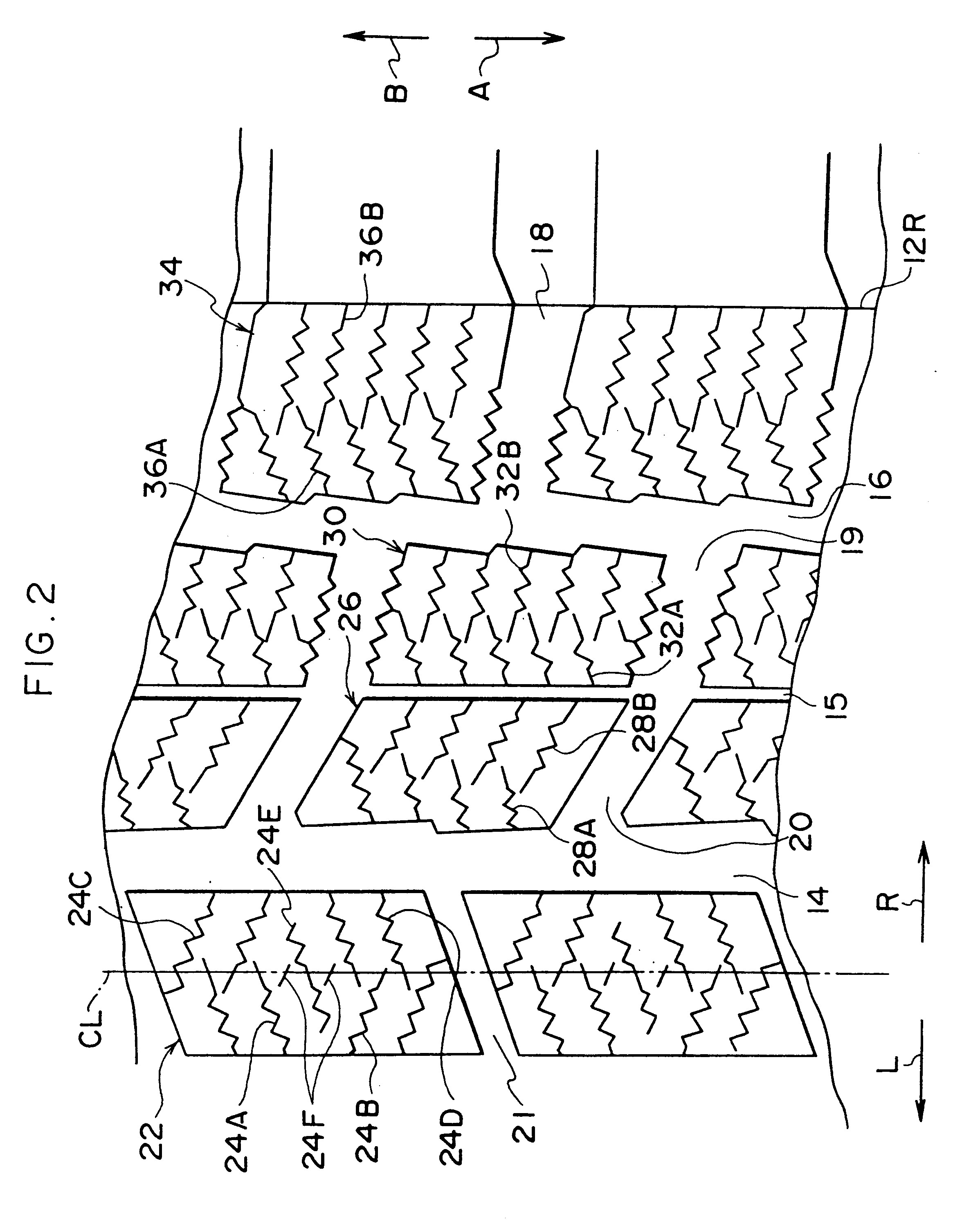
a pneumatic tire 10 in accordance with the present invention will be described with reference to FIGS. 1 and 2.

In FIG. 1, the arrow L and the arrow R show the leftward direction and the rightward direction, respectively, of the tire (both directions may be referred to as the axial direction of the tire). The arrow A and the arrow B shows the direction of rotation of the tire and the direction of tire travel relative over a ground surface, respectively, for the lowest portion of the tire (both directions may be referred to as the circumferential direction of the tire).

As shown in FIG. 1, in the tread 12 (W represents the width of the tread) of the pneumatic tire 10 of the present invention, circumferential broad grooves 14 extend in the circumferential direction of the tire at both sides of the tire equatorial center line ("CL") plane. At the tire axial direction outer side of each circumferential broad groove 14, circumferential narrow grooves 15 extend substantially in the circumfe...

examples 4 to 8

Pneumatic tires having a size of 225 / 50R16 and the tread pattern shown in FIG. 8 were prepared for the conditions shown in Table 3. The prepared tires were attached to rims having a size of 7J and inflated at an inner pressure of 200 kPa. The tires were mounted on a vehicle, subjected to the road test and evaluated with respect to properties on snow such as the acceleration and cornering properties, properties on ice, properties on dry road surfaces such as the braking and controllability and properties on wet road surfaces such as braking and controllability based on the feel. The methods of the evaluation were the same as those described above except that the result was expressed as an index using the result of the tire of Example 4 which was set at 100. The tire of Examples 4 to 8 had the tread having the block pattern shown in FIGS. 29 to 33, respectively. The greater the number, the better the result. The results are shown in Table 3.

TABLE 3 Exam- Exam- Exam- Exam- Exam- ple 4 ...

examples 9 to 12

Pneumatic tires having a size of 225 / 50R16 and the tread patterns shown in FIGS. 10A, 10B and 10C were prepared for the conditions shown in Table 4. The prepared tires were attached to rims having a size of 7J and inflated to an inner pressure of 200 kPa. The tires were attached to a vehicle, subjected to the road test and evaluated with respect to properties on snow such as the acceleration and cornering properties, properties on ice, properties on dry road surfaces such as braking and controllability and properties on wet road surfaces such as the braking and controllability based on the feel. The methods of the evaluation were the same as those described above. The methods of the evaluation were the same as those described above except that the result was expressed as an index using the result of the tire of Example 9 which was set at 100. The tire of Examples 9 to 12 had the tread having the block pattern shown in FIGS. 29 and 34 to 36, respectively. The greater the number, the ...


PUM


Abstract

Sipes extending from one end of a block to the central area of the block and sipes extending from the other end of the block to the central area of the block (sipes 24, 28, 32 and 36) are inclined in directions opposite to each other. The sipes extending from one end of the block and the sipes extending from the other end of the block intersect a common line extending along the circumferential direction of the tire. Due to this structure, the number of portions of the sipes, which portions are located in the central area of the block, is made greater than that in the peripheral area of the block. The density of sipes is thus increased in the central area of a block where water tends to form when driving on ice, for improving braking and traction properties on ice.

Description

BACKGROUND OF THE INVENTION1. Field of the InventionThe present invention relates to a pneumatic tire and more particularly to a pneumatic tire having a tread with a block pattern.2. Description of the Related ArtSipes formed in ribs and blocks of a tread exhibit the effect of cutting through water films on road surfaces, similar to edges of grooves. The sipes also facilitate deformation of ribs and blocks and help exhibition of rubber hysteresis loss. Therefore, sipes are widely used in studless tires.As shown in FIG. 3, studless tires generally have zigzag or straight sipes 100, extending substantially parallel to tire circumferential-direction end portions of blocks (i.e., the end portions of blocks which are continuous with the block end portions running along the circumferential direction of the tire). Alternatively, as shown in FIG. 26, studless tires generally have sipes 102 which are approximately perpendicular to the circumferential direction of the tire in each block 101.H...

Claims


Application Information

Patent Timeline
IPC IPC(8): B60C11/12B60C11/13B60C11/11
CPCB60C11/11B60C11/12B60C11/13B60C11/1263B60C11/1315B60C2011/147B60C2011/1245Y10S152/03Y10S152/902B60C2011/1213
Inventor OCHI, NAOYAKIMURA, MASAHARUKUROKAWA, MAKOTOKAWABE, HIROSHIYOSHIDA, HIROTO
Owner BRIDGESTONE CORP
Why Eureka
Try Eureka