Supercharge Your Innovation With Domain-Expert AI Agents!

Detection system

a detection system and detection technology, applied in the field of detection systems, can solve the problems of large loss of cooling efficiency, large amount of energy required to operate the system, and the inability of the cooling technology of the peltier to achieve such low temperatures

Inactive Publication Date: 2003-06-03
OXFORD INSTR NANOTECH TOOLS
View PDF5 Cites 6 Cited by
  • Summary
  • Abstract
  • Description
  • Claims
  • Application Information

AI Technical Summary

Benefits of technology

The invention provides a number of benefits. Firstly, by positioning the pulse tube cooler within the housing, it can be inserted into, typically the vacuum enclosure of, a microbeam instrument.
The pulse tube cooler usually includes a cold heat exchanger with the sensor being attached to the cold heat exchanger via a short thermally conductive coupling. Minimizing the length of thermally conductive elements to couple the sensor to the cold heat exchanger increases the cooling efficiency of the system.

Problems solved by technology

Current commercial peltier cooling technology does not allow such low temperatures to be achieved.
However, this suffers from the major drawback that the sensor is cooled by the cold finger which results in a large loss in cooling efficiency.
Firstly, a larger amount of energy is required to operate the system.
Secondly, the compressor which drives the pulse tube cooling system must be of a sufficiently large size to obtain the cooling power.
In order to achieve this, at least one rotating valve is required to couple the compressor to the pulse tube which in turn leads to further losses in efficiency.
Accordingly, this suffers from similar problems to those outlined above with respect to the system described in GB-A-2325045.
Secondly, positioning the sensor and the pulse tube cooler together inside the housing reduces the cooling effect required by the pulse tube cooler to keep the sensor at the desired temperature.

Method used


Image

  • Detection system
  • Detection system

Examples


Embodiment Construction

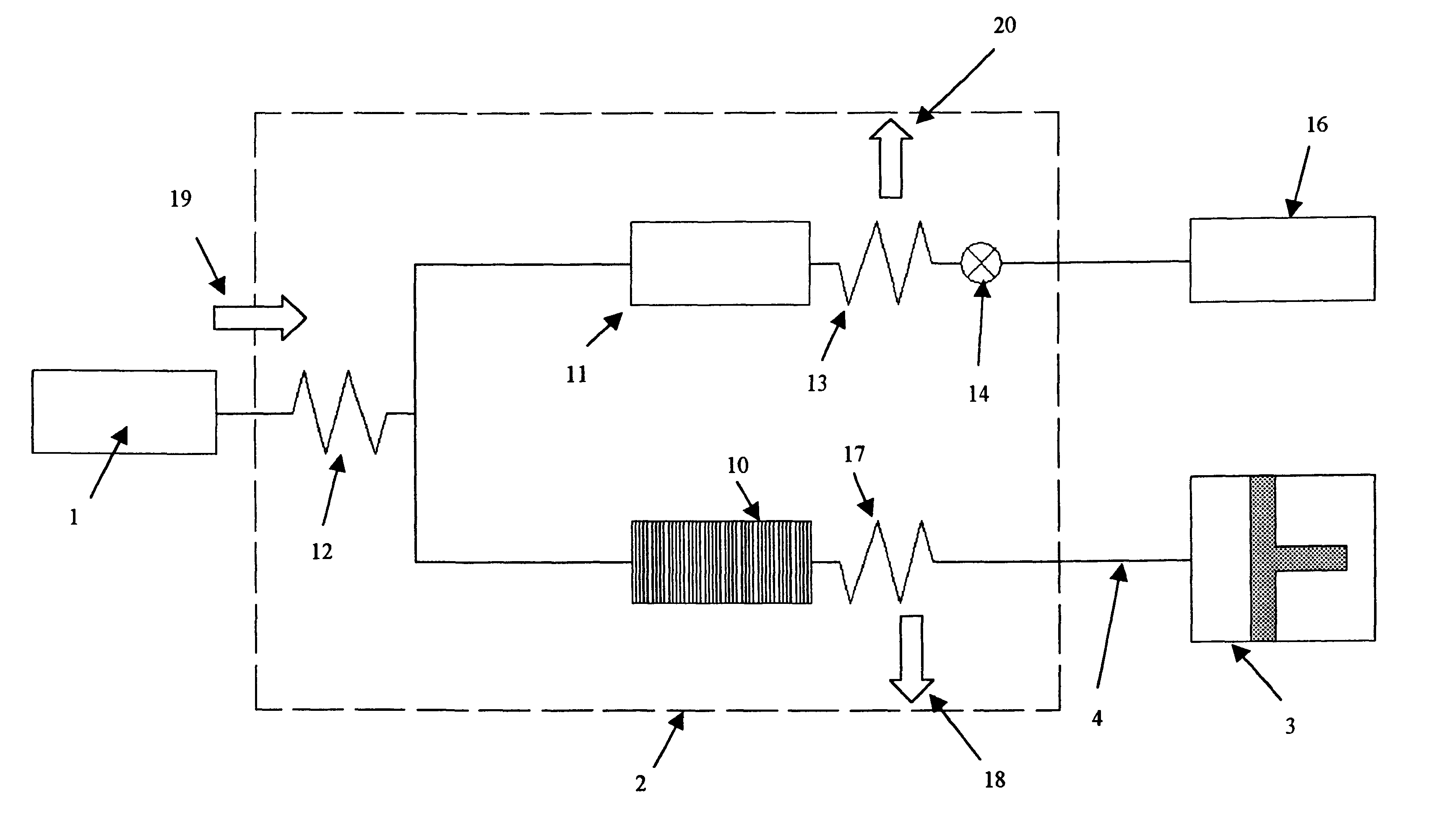
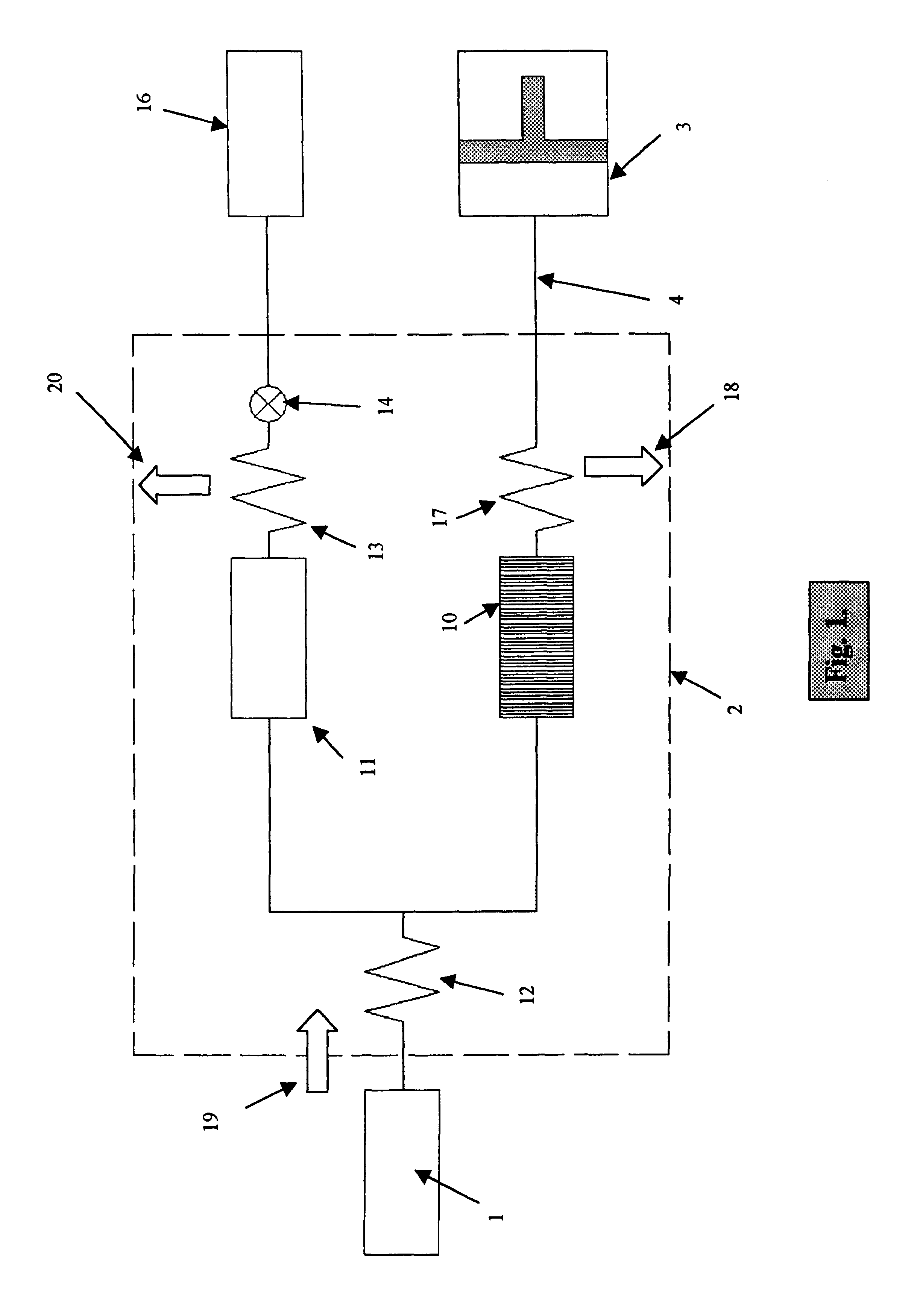
As shown in FIG. 1, the detection system includes an X-ray sensor 1 of conventional form coupled to a pulse tube cooler 2 which is in turn coupled to a compressor 3, via a continuous connecting pipe 4.

The pulse tube cooler 2 is typically an orifice pulse tube cooler which comprises a regenerator 10 and a pulse tube 11 coupled together via a cold end heat exchanger 12. The pulse tube is coupled to a hot end heat exchanger 13 which is in turn connected to an orifice 14. The orifice is used to connect the hot end heat exchanger 13 to a reservoir 16.

The operation of the pulse tube cooler 2 is roughly comparable to a Stirling cycle cooler which has no moving parts in the cold section. This means there is no frictional wear so that the low temperature sections have an infinite lifetime. Essentially there is no vibration induced in the cold section.

In use, the compressor 3 is used to compress a working gas, such as He. The compressed working gas flows along the continuous connecting pipe 4...


PUM

PropertyMeasurementUnit
outer diameteraaaaaaaaaa
temperatureaaaaaaaaaa

Abstract

A detection system for detecting X-ray radiation from a sample located in a microbeam instrument. The detection system comprises:a. a pulse tube cooler;b. a compressor connected to the pulse tube cooler;c. a sensor coupled to the pulse tube cooler; and,d. a housing containing the pulse tube cooler and the sensor. The pulse tube cooler, the sensor and at least part of the housing are sufficiently small to be positioned inside the microbeam instrument in use, thereby allowing the X-ray radiation from the sample to be detected by the sensor.

Description

The present invention relates to a detection system for detecting X-ray radiation from a sample located in a microbeam instrument.DESCRIPTION OF THE PRIOR ARTMicrobeam instruments comprise a vacuum within which a sample that emits X-rays is located and include scanning electron microscopes (SEMs), transmission electron microscopes (TEMs), scanning transmission electron microscopes (STEMs), electron probe microanalysers (EPMAs) and defect review tools (DRTs).In such detection systems, it is typically necessary to cool the sensor down to a temperature of around 90K. In the past, this has typically been achieved by connecting a large reservoir of liquid nitrogen to the sensor by a series of copper components. The copper components then operate to transfer heat from the sensor to the liquid nitrogen reservoir thereby maintaining the sensor at an operating temperature.In recent years however, there has been a shift in design to replace the liquid nitrogen reservoir by a cooling device th...

Claims


Application Information

Patent Timeline
Patent Type & Authority Patents(United States)
IPC IPC(8): G01T1/00G01T7/00G01T1/24H01J37/244H01J37/256H01J37/252F25B9/00
CPCF25B9/145G01T1/244G01T7/00H01J37/244H01J37/256F25B9/10F25B2309/1408F25B2309/1413F25B2309/1424H01J2237/2555F25D19/006
Inventor RADLEY, IANBHADARE, SANTOKH SINGHTYRRELL, CHRISTOPHER
Owner OXFORD INSTR NANOTECH TOOLS
Features
  • R&D
  • Intellectual Property
  • Life Sciences
  • Materials
  • Tech Scout
  • Unparalleled Data Quality
  • Higher Quality Content
  • 60% Fewer Hallucinations
Learn More