Ring shaped spring device

a spring device and ring technology, applied in the direction of wound springs, low internal friction springs, mechanical devices, etc., can solve problems such as damage and/or unintended biasing forces

Inactive Publication Date: 2003-06-10
BARNES GROUP
View PDF7 Cites 26 Cited by
  • Summary
  • Abstract
  • Description
  • Claims
  • Application Information

AI Technical Summary

Benefits of technology

The present invention relates to a ring-shaped spring device as shown in Orlowski 5,306,086, wherein there are a plurality of guide assemblies located at circumferentially spaced positions around the ring. Each of these guide assemblies includes a first tab extending from one of the plates toward the other plate, a second tab extending in the opposite direction from the other plate to form a generally sliding contact between the first and second tabs as the spaced plates move vertically to compress and release the coil springs. The first tab has a guide slot with a given width. The slot extends in a direction perpendicular to the plates. The second tab carries an assembled elongated guide member extending radially through the guide slot to positively guide the vertical movement between the two plates. There is no integral interconnecting means, since the two tabs of the plates are joined together by a third member which is an assembled elongated guide member. The guide slot has an end remote from the plate from which the second tab extends. The distance of this end from the plate causes compression of the coil springs by the action of the guide member when the device is assembled. Thus, the springs are positioned between the two annular plates and the plates are oriented with the spaced tabs of one plate in sliding contact with the spaced tabs on the other plate. The springs are then compressed and the elongated guide member is press fitted through one tab and extends into the guide slot of the other tab. To support the guide member, the second tab includes a bore defined by an extruded boss that allows a press fit of the guide member in the boss to maintain the guide member in the proper horizontal position. The structure assembly procedure and operation of the present invention is different than the ring shaped spring device in Orlowski 5,306,086. These added features result in the advantage of being capable of maintaining the proper annular orientation between the spaced plates during long term operation of the spring device in an automatic transmission.

Problems solved by technology

However, when assembled in a transmission, the ring shaped spring device is compressed further so that the hook actually disengages the loop.
Consequently, during repetitive operation of the spring assembly over many years, the individual coil springs can become canted in a manner to reduce the spring constant and cause damage and / or unintended biasing forces.
Consequently, the prior ring shaped spring device, as shown in Orlowski 5,306,086 only employs the concept of integral interconnecting means and does not address the problem of controlling the annular movement of the spaced plates during long term operation of the spring device.

Method used


Image

  • Ring shaped spring device
  • Ring shaped spring device
  • Ring shaped spring device

Examples


Embodiment Construction

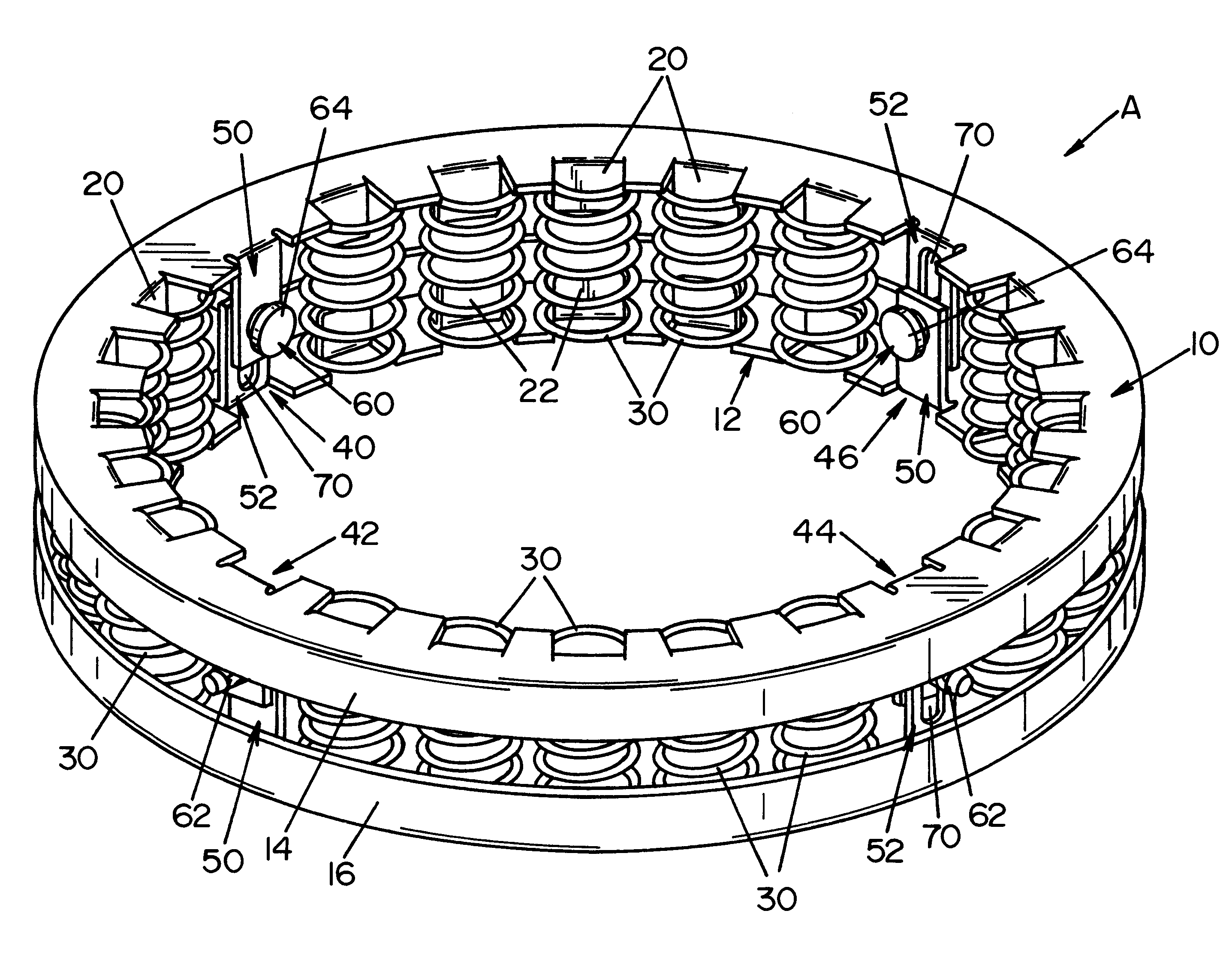
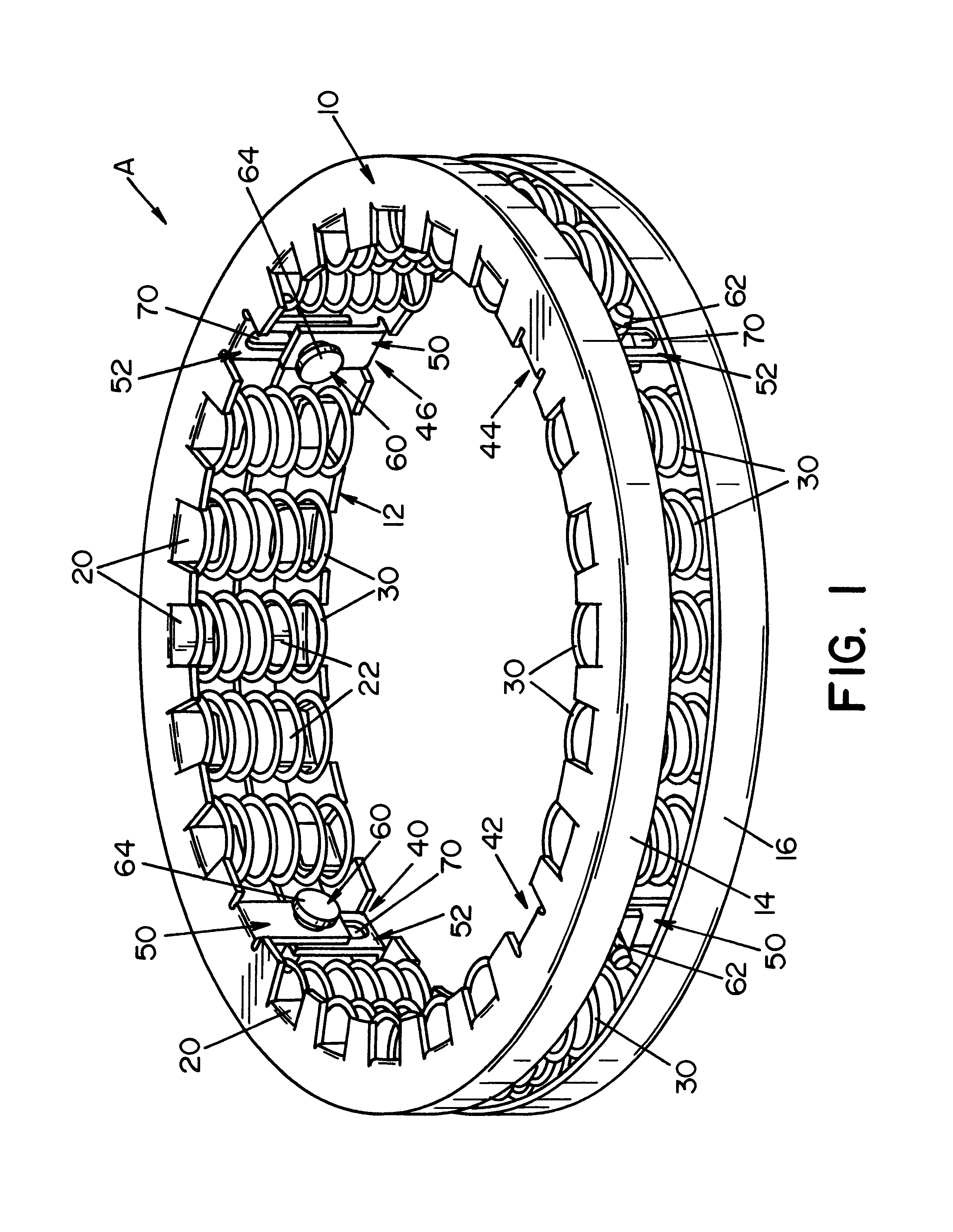
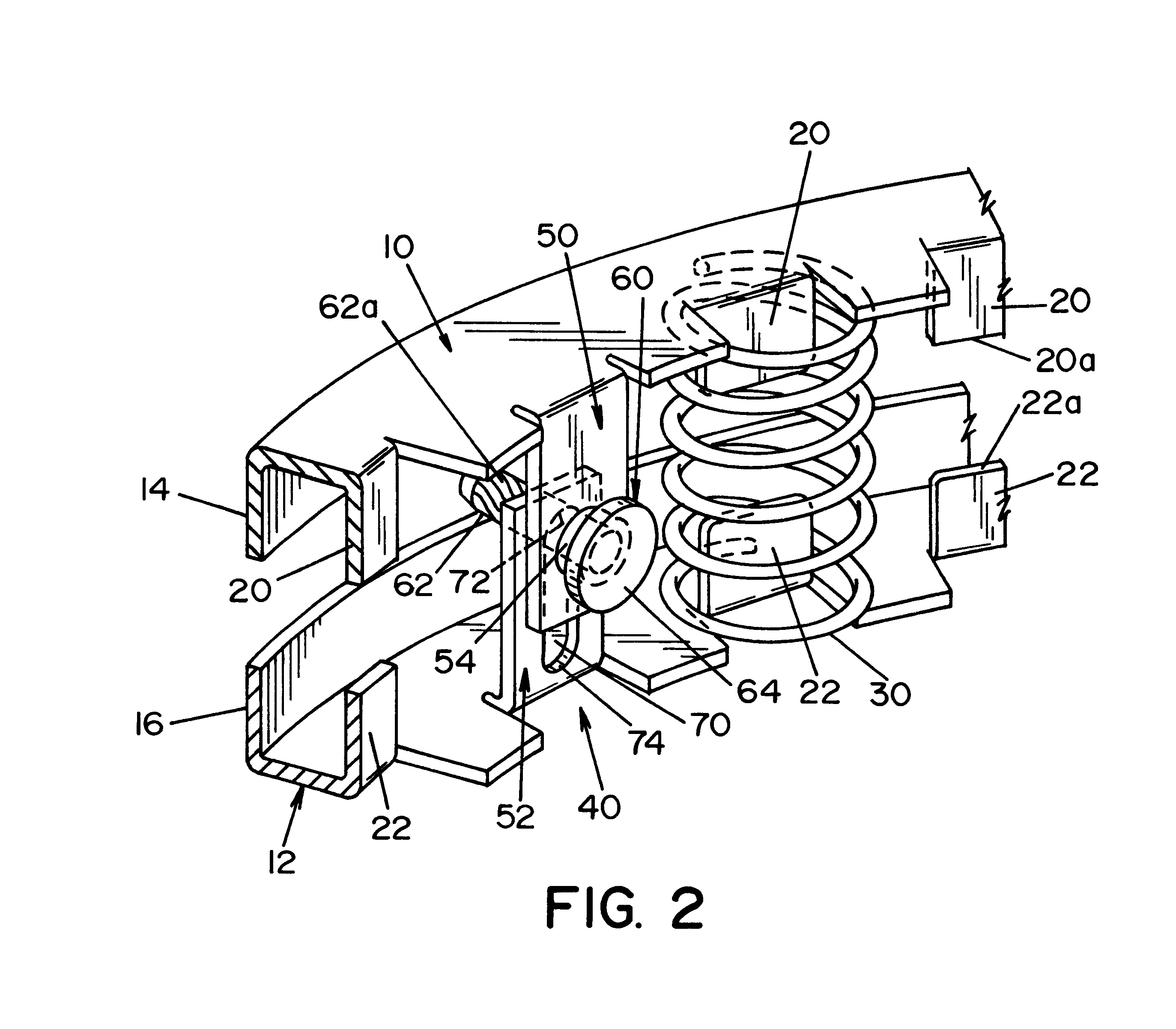
Referring now to the drawings, wherein the showings are for the purpose of illustrating a preferred embodiment of the invention only and not for the purpose of limiting same, FIG. 1 and FIG. 3 show annular spaced-apart plates 10, 12 with outer rims 14, 16, respectively. Bent edge tabs 20 of plate 10 and tabs 22 of plate 12 are bent downwardly to locate at circumferentially spaced positions a number of coil springs 30. The spring supporting tabs 20, 22 are best shown in FIGS. 2, 4, 6 and 7. They have spaced edges 20a, 22a with a gap therebetween. The height of the integral lanced tabs 20, 22 maintain a gap between edges 20a, 22a. The width W of the spring locating tabs, as shown in FIG. 7, are just slightly larger than the diameters of the center passage of springs 30. Any number of tabs and springs can be circumferentially spaced around plates 10, 12. In the preferred embodiment, twenty springs are employed and located in groups of five. Four guide assemblies 40, 42, 44 and 46 are p...


PUM


Abstract

A spring device comprising a pair of spaced-apart first and second annular support plates defining a ring with a central axis; a plurality of circumferentially spaced, parallel oriented coil springs disposed between said annular plates; and, a plurality of guide assemblies located at circumferentially spaced positions around said ring, each of the guide assemblies including a first tab extending from one of the plates, a second top extending from the other of the plates to form a generally sliding contact between the first and second tabs as the plates move vertically to compress and/or release the coil springs wherein the first tab has a guide slot extending in a direction perpendicular to the plates and the second tab carries an assembled elongated guide member extending through the slot to guide vertical movement between the plates.

Description

The present invention relates to a spring device and more particularly to a spring device of the type used in automatic transmissions for motor vehicles.INCORPORATION BY REFERENCEAutomatic transmissions for vehicles often include a plurality of coil springs that are adapted to apply a biasing force against clutch plates that control the engagement of various gears in the transmission. These coil springs are assembled in a ring shaped device comprising two annular plates having a multiplicity of circumferentially spaced, parallel compression coil springs mounted therebetween. Such a ring shaped spring device is disclosed in Orlowski 5,306,086, which is incorporated by reference herein as the basic background to which the present invention is directed.BACKGROUND OF INVENTIONIn the ring shaped spring device disclosed in Orlowski 5,306,086, there is a pair of spaced apart first and second annular support plates defining the ring shape of the spring device. A plurality of circumferential...

Claims


Application Information

Patent Timeline
Patent Type & Authority Patents(United States)
IPC IPC(8): F16F3/04F16F1/04F16F1/12F16F3/00
CPCF16F1/128F16F3/04F16F2230/0052
Inventor COSTELLO, PHILIP G.HROVAT, FRANK R.
Owner BARNES GROUP
Why Eureka
Try Eureka