Firearm safety device

a safety device and firearm technology, applied in the field of firearm safety, can solve the problems of increased cost, children and other people being injured or killed, and gun owners not enthusiastic about using smart guns

Inactive Publication Date: 2003-06-17
HICKERSON FREDERICK R
View PDF26 Cites 16 Cited by
  • Summary
  • Abstract
  • Description
  • Claims
  • Application Information

AI Technical Summary

Benefits of technology

It is a further object of my invention to provide a firearm safety device which can be positioned on new and used handguns of any caliber and any barrel length using a minimum of different components in order to enhance production and marketing.
Another object of my invention is to provide such a firearm safety device which is installable and removable entirely from the muzzle end of a gun barrel, without any scratching or other damage to the firearm.
Yet another object of my invention is to provide a firearm safety device of simple, rugged construction and with a high reliability of working properly.
Still another object of my invention is to provide a firearm safety device, which can be totally or partially made of tough plastic material, which can be inexpensively molded using current production machines and techniques.
A further object of my invention is to provide a firearm safety device which is childproof but can be removed from a firearm by an adult in 5 to 10 seconds, in pitch darkness by using only a small physical force.

Problems solved by technology

Children and other people are injured or killed by accidental shootings from loaded firearms which do not have preventative safety devices and which have been carelessly placed or stored where children can gain access to them.
Gun owners are not enthusiastic about using smart guns, with batteries, electronics and magnets, because of the added cost and their questionable reliability for functioning properly and timely in emergency situations.
Most gun owners will remove, or not install, these safety devices on a firearm which is positioned for emergency use, since all known marketed safety devices require unacceptable delays to ready for use.
The child might then continue to monkey around the trigger or drop the gun possibly causing it to fire.
While some states mandate trigger lock devices for guns that are sold, these devices don't solve the real problem of child proofing all handguns in a manner that the gun owner can, in an emergency, easily remove the safety device in 5 to 10 seconds in pitch darkness, i.e. to defend oneself and family
The amount of time required to find and use the key rod to remove the block from the gun barrel, remove the dummy cartridge and load the gun is not acceptable to the gun owner in an emergency situation.
The disadvantage of the cable locks and other barrel blockers is their requirement for keys, combinations, special key rods and the like, which cause an unacceptable delay for the gun owner in removal of the safety device in emergency situations, where every second counts.
All other known barrel block safety devices that go through the barrel and into the firing chamber have a removal system requiring a key rod, a cable, or a digital padlock, which causes an unacceptable delay for the gun owner in an emergency situation.
These devices, which are relatively complex mechanically and expensive are better from a safety standpoint than the trigger lock device.
Since the safety device is able to rotate freely in its assembled position in the gun, any attempt to unscrew the knurled cap without holding the knurled enlarged end portion of the lock sleeve stationary will be unsuccessful.
A child will not be able to remove the knurled cap since he or she will hold the gun in one hand while fiddling with the knurled cap with the other hand.
Many other firearm safety devices such as clam shell type trigger lock, barrel locks, and trigger blocks are not designed to prevent a cartridge from being in the firing chamber, and for this reason are considered dangerous.

Method used


Image

  • Firearm safety device
  • Firearm safety device
  • Firearm safety device

Examples


Embodiment Construction

. 1-5

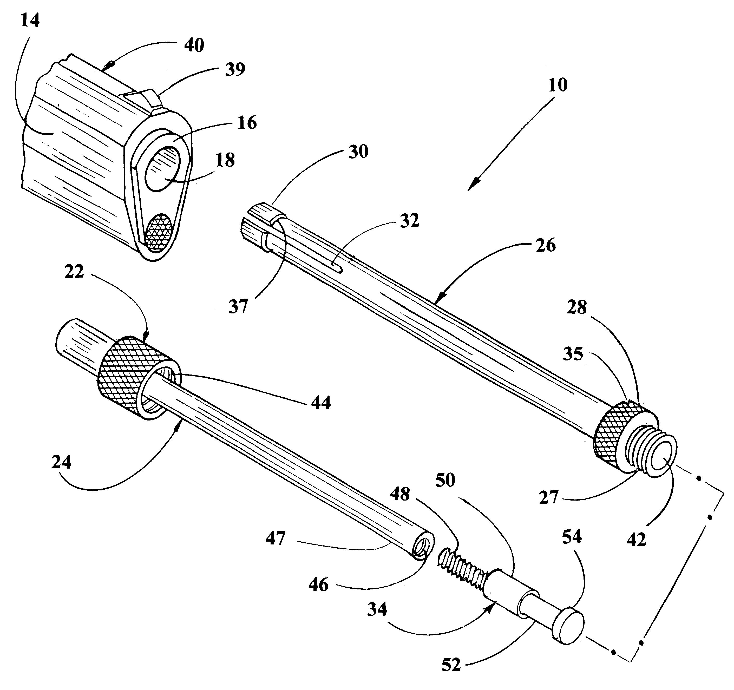
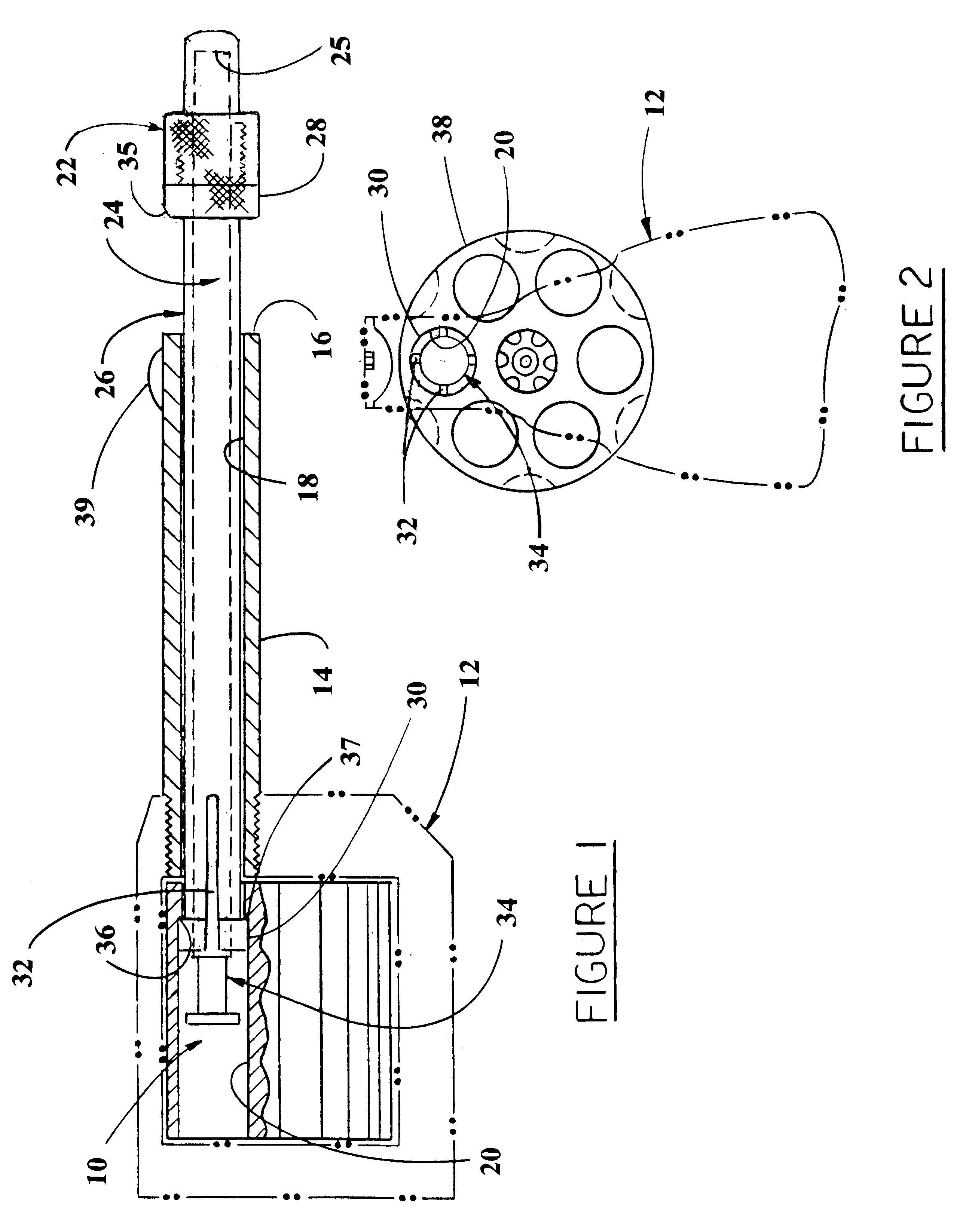
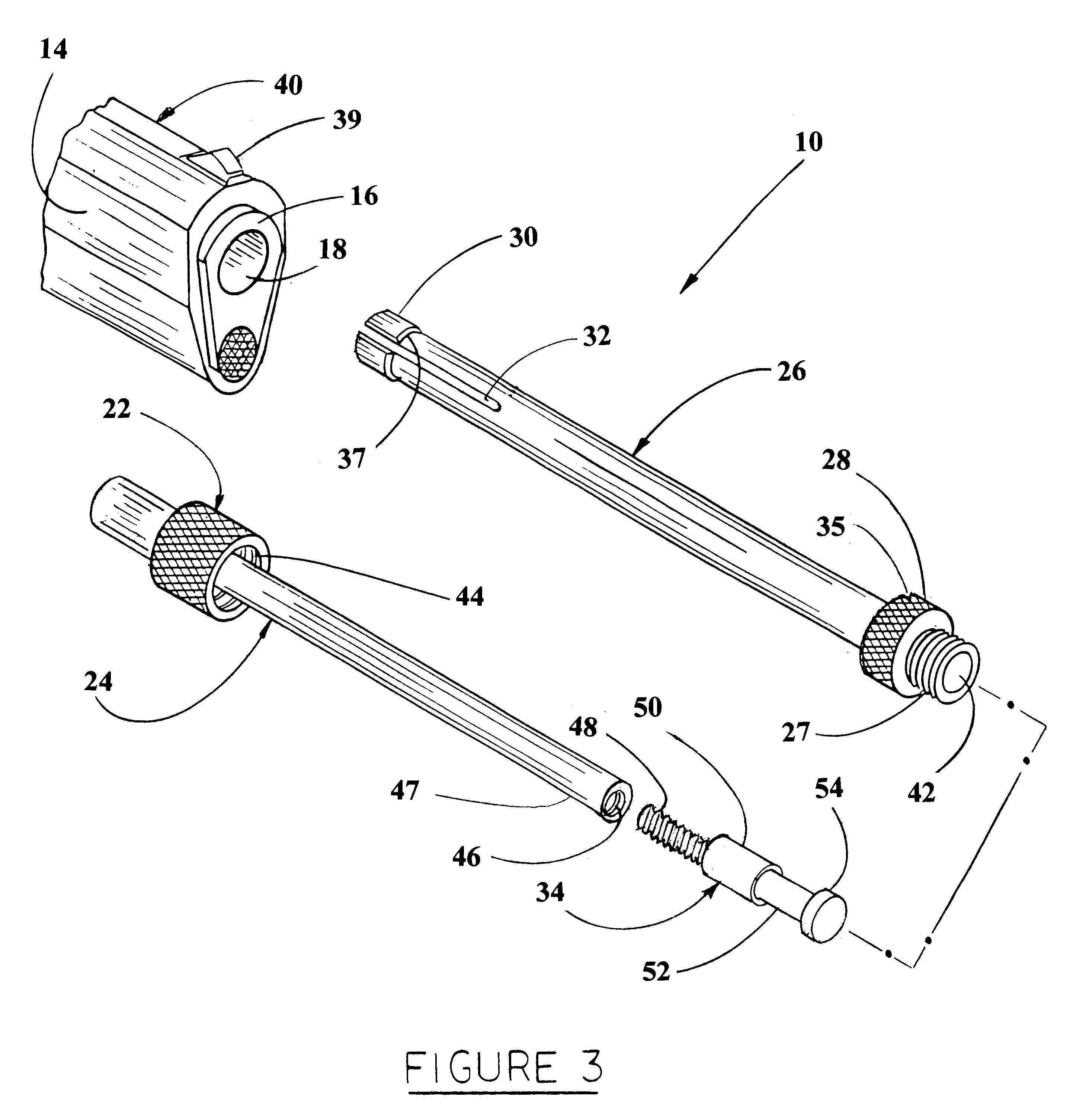
Referring now to the drawings and more particularly FIG. 1, it can be seen that a firearm safety device according to the invention is designated generally by the numeral 10. As will become apparent herein, firearm safety device 10 is intended to serve as a firing chamber block mechanism, securing the barrel and firing chamber of the firearm on which it is employed. Firearm safety device 10 shown in the assembly drawing of FIG. 1, for a revolver handgun 12, has a barrel 14 extending to a muzzle 16. A bore 18 extends axially into barrel 14 from muzzle 16 in standard fashion. As will become further apparent herein, bore 18 typically terminates at a firing chamber 20 of a revolver handgun 12.

Firearm safety device 10 includes a knurled cap 22 with a lock rod 24, securely fastened into a circular cavity 25 of knurled cap 22. As shown, lock rod 24 is inside a lock sleeve 26 which is assembled in bore 18. Knurled cap 22 is threaded to a mating thread 27 on a knurled enlarged end portio...


PUM


Abstract

An improved firearm safety device for handguns is disclosed. The firearm safety device (10) prevents accidental firing of a gun by children, but is easily removable by an adult in 5 to 10 seconds, even in pitch darkness. The firearm safety device includes a lock sleeve (26) having an expandable end plug (30) and a lock rod (24) having a removable tip (34), which are inserted through muzzle (16) of a gun barrel (14) into an empty firing chamber (20). Removable tips, having different diameters, provide the proper expansion for different caliber handguns. A knurled cap (22), connected to the lock rod, is threadedly attached to a knurled enlarged end portion (28) of the lock sleeve, forcing the expansion of the linear slotted (32) end plug, preventing removal of the firearm safety device from the handgun. Since the safety device is able to rotate freely in its assembled position within the handgun, any attempt to unthread the knurled cap without holding the knurled enlarged end portion of the lock sleeve stationary, will be unsuccessful.

Description

1. Field of InventionThis invention relates to safety for firearms, specifically a device to securely block the chamber and barrel of a firearm to prevent its firing.2. Description of Prior ArtChildren and other people are injured or killed by accidental shootings from loaded firearms which do not have preventative safety devices and which have been carelessly placed or stored where children can gain access to them. It has been estimated that Americans keep 200 million handguns in their homes.Inventors and firearms manufacturers are working to develop and market "Personalized Smart Guns", ones that only the owner can fire. Smart gun inventions disclose a wide variety of safety lock systems, including thumb print recognition, ring or wristwatch radio controlled device, keypunch lock control and magnetic ring control. Gun owners are not enthusiastic about using smart guns, with batteries, electronics and magnets, because of the added cost and their questionable reliability for functio...

Claims


Application Information

Patent Timeline
Patent Type & Authority Patents(United States)
IPC IPC(8): F41A29/00F41A17/44F41A17/00F41A29/02
CPCF41A29/02F41A17/44
Inventor HICKERSON, FREDERICK R.
Owner HICKERSON FREDERICK R
Why Eureka
Try Eureka