
Hydromechanical system for limiting excess engine speed

a hydraulic system and engine technology, applied in mechanical devices, machines/engines, electric control, etc., can solve the problems of loss of aircraft, likely to perforate the engine casing with consequences, etc., and achieve the effect of reducing the operating speed, restoring the engine to operability, and reducing the drawbacks

Inactive Publication Date: 2003-06-17
HISPANO SUIZA SA
View PDF7 Cites 8 Cited by
  • Summary
  • Abstract
  • Description
  • Claims
  • Application Information

AI Technical Summary

Benefits of technology

The present invention thus proposes mitigating those drawbacks by means of an electronic system for providing protection against excess speeds which does not lead to the engine being completely stopped, and which also guarantees a minimum operating speed for maintaining all of the equipment of the aircraft. Another object of the invention is to enable the pilot to act directly on the system in order to unlock it and thus restore the engine to operability.

Problems solved by technology

Unfortunately, such a loss is likely to perforate the engine casing with consequences that can be as bad as complete destruction of the turbomachine.
However, nowadays, such mechanical regulators are being replaced progressively by electronic regulators which act directly on the engine by interrupting the fuel supply to the combustion chamber of the turbomachine.
Unfortunately, that solution suffers from the severe drawback of requiring a restart procedure to be engaged subsequently which, under certain particular conditions of flight, e.g. takeoff, can turn out to be impossible to implement and can lead inevitably to loss of the aircraft.

Method used


Image

  • Hydromechanical system for limiting excess engine speed
  • Hydromechanical system for limiting excess engine speed
  • Hydromechanical system for limiting excess engine speed

Examples


Embodiment Construction

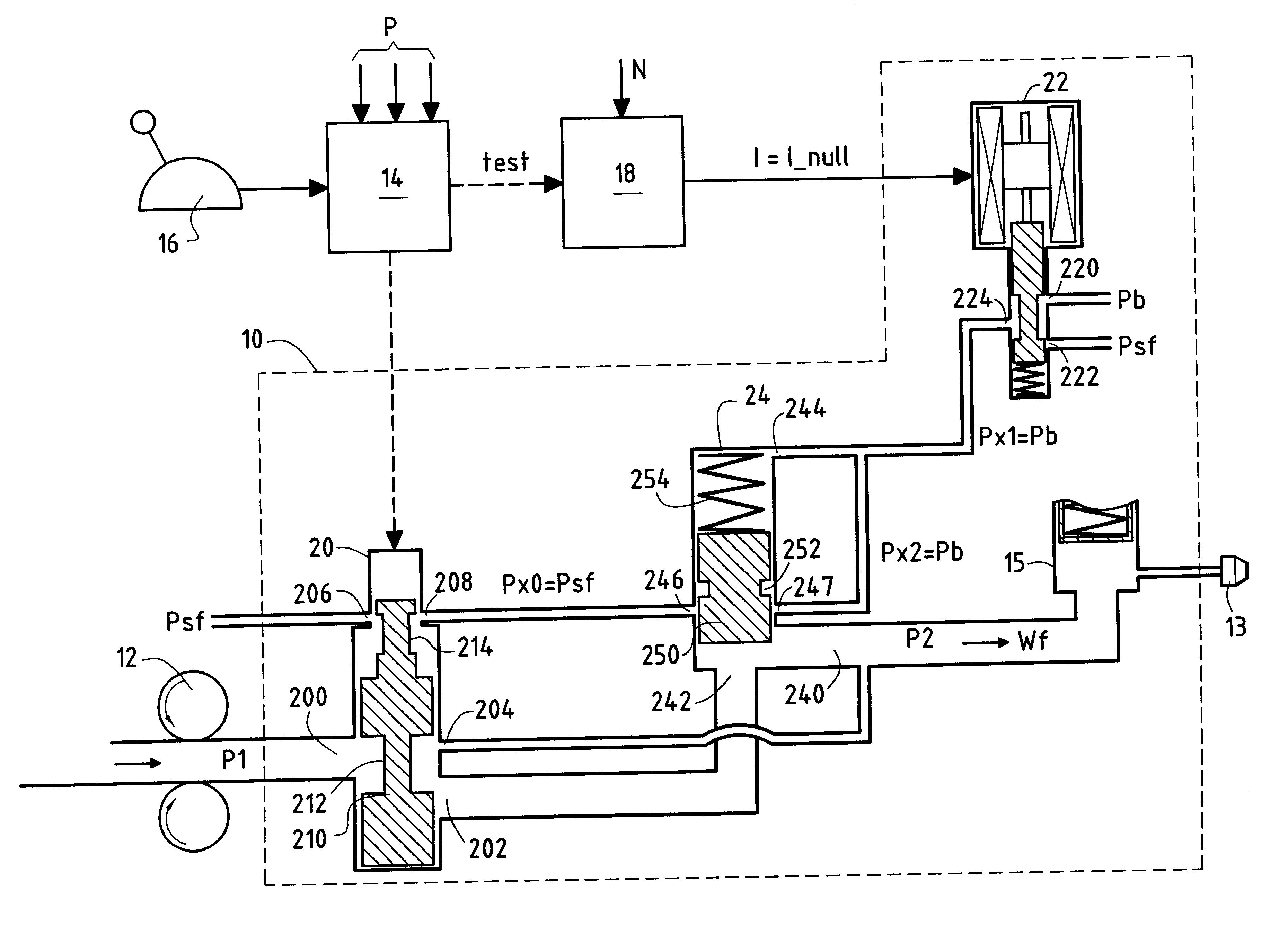
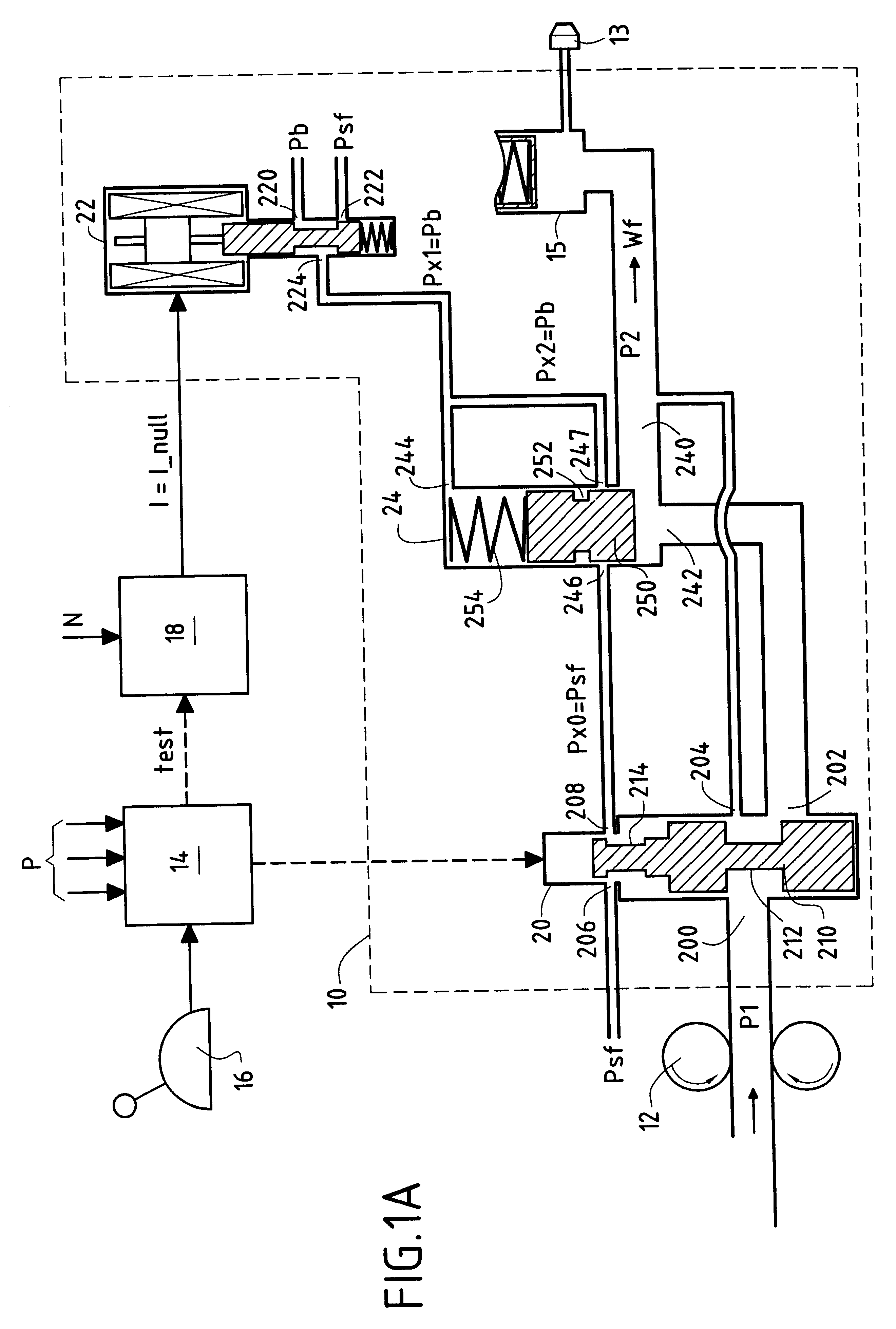
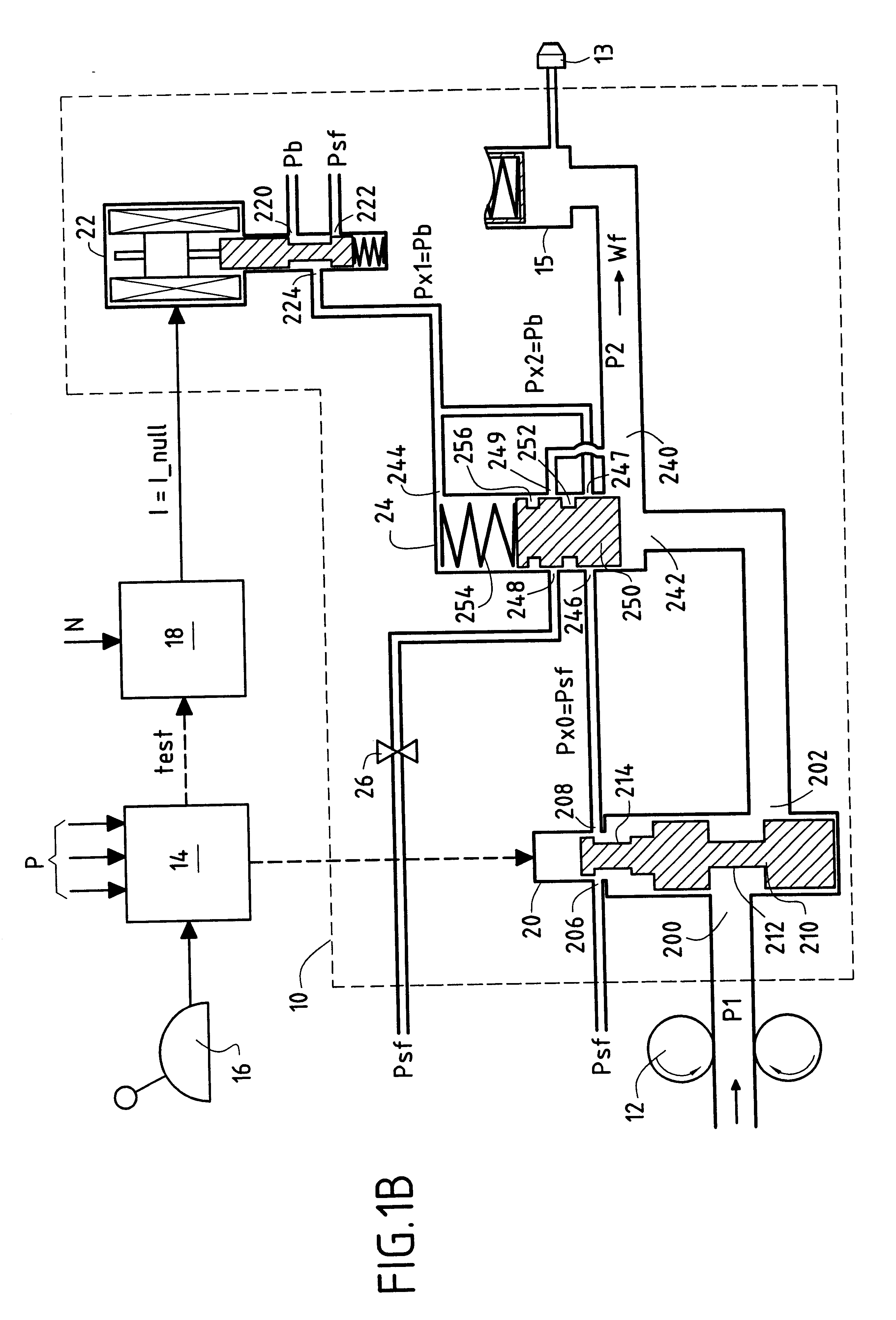
A diagrammatic view of a portion of a fuel injection system for an aircraft turbomachine is shown in FIGS. 1A and 1B.

In general, such a fuel injection system is organized around a fuel metering unit (FMU) 10 for controlling the flow rate of fuel that flows between a high pressure pump 12 for pressurizing the fuel taken from a fuel tank (not shown) and a plurality of fuel injectors 13 for the combustion chamber of said turbomachine at the inlets of which there are disposed respective shut-off valves 15 controlled by corresponding shut-off solenoid valves. The high pressure HP at the outlet from the high pressure pump is referenced P1 and the pressure at the inlet to the injectors is referenced P2. The fuel flow rate supplied by the metering unit (engine regulation) is continuously controlled by an electronic control circuit 14 to which said unit is connected, said control being a function of engine parameters P and of the position of a throttle control lever 16 actuated by the pilot ...


PUM


Abstract

In a turbomachine whose speed of rotation is controlled by means of a throttle control lever acting via an electronic control circuit, a system is provided to provide protection against excess speed, the system comprising means for limiting the fuel feed of the turbomachine to a predetermined fixed flow rate Wps when the speed of rotation exceeds an authorized maximum speed, means for maintaining said fuel feed at said predetermined fixed flow rate while the speed of rotation drops below the authorized maximum speed, and means for reducing said fuel speed to a flow rate Wr corresponding to an idling speed when the throttle control lever issues an idling control to the turbomachine via the electronic control circuit.

Description

The present invention relates to the field of injecting fuel into turbomachines, and it relates more particularly to a system for protecting against excess speed.PRIOR ARTIn turbomachines, best performance is obtained at speeds of rotation of the rotary members that are close to the maximum acceptable limits, beyond which a compressor or turbine blade might be lost. Unfortunately, such a loss is likely to perforate the engine casing with consequences that can be as bad as complete destruction of the turbomachine.Thus, and as recommended by international regulations concerning civil aviation, it is essential to use a system to provide protection against excess speeds so as to ensure that the speed of said rotary members does not exceed such authorized maximum speeds.Until recently, these protection systems made use of regulators of the same type as the Watt fly-weight governor, as shown in international application No. WO 89 / 02980. However, nowadays, such mechanical regulators are be...

Claims


Application Information

Patent Timeline
Patent Type & Authority Patents(United States)
IPC IPC(8): F02C9/28F02C9/00F02C9/46F02D45/00F02D23/02F02D41/02F02D41/22
CPCF02C9/28F02C9/46F05D2270/021
Inventor MAILLARD, DAVIDGARASSINO, ALAINMAILLARD, CLAUDEDESSENNE, CAROLINEVEGIOTTI, ISABELLE
Owner HISPANO SUIZA SA
Learn More