Liquid fuel burner

a technology of liquid fuel burner and burner, which is applied in the direction of burners, combustion types, combustion processes, etc., can solve the problems of not being able to easily adapt to use with pre-existing bases, statuaries and the lik

Inactive Publication Date: 2003-06-17
TAUBITZ ROBERT +2
View PDF18 Cites 46 Cited by
  • Summary
  • Abstract
  • Description
  • Claims
  • Application Information

AI Technical Summary

Benefits of technology

It is another object of the invention to provide a liquid fuel burner which can be used with a variety of holders, including statuary, and which can be easily refilled and reused. The fuel burners intended herein can be easily and conveniently fitted into existing hollow statues, bases or holders, without substantial modification thereto. Thus, each individual object need not be specially designed or configured to receive the burner.
It is a further feature of the invention to provide a liquid fuel burner which minimizes the hazard of fire caused by accidental spills and leaks.
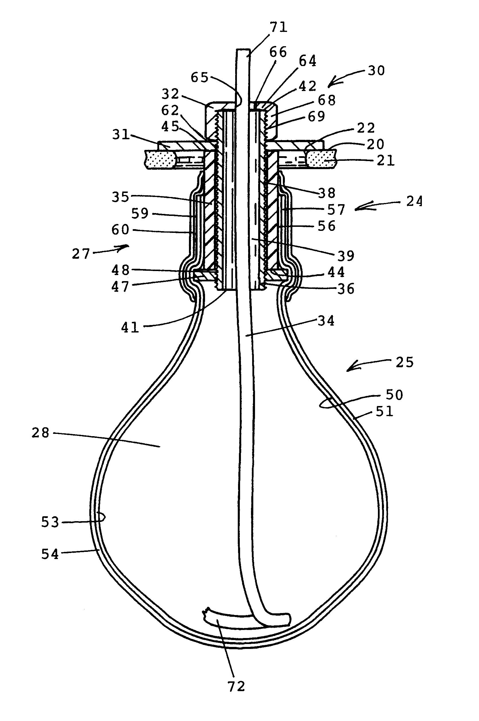
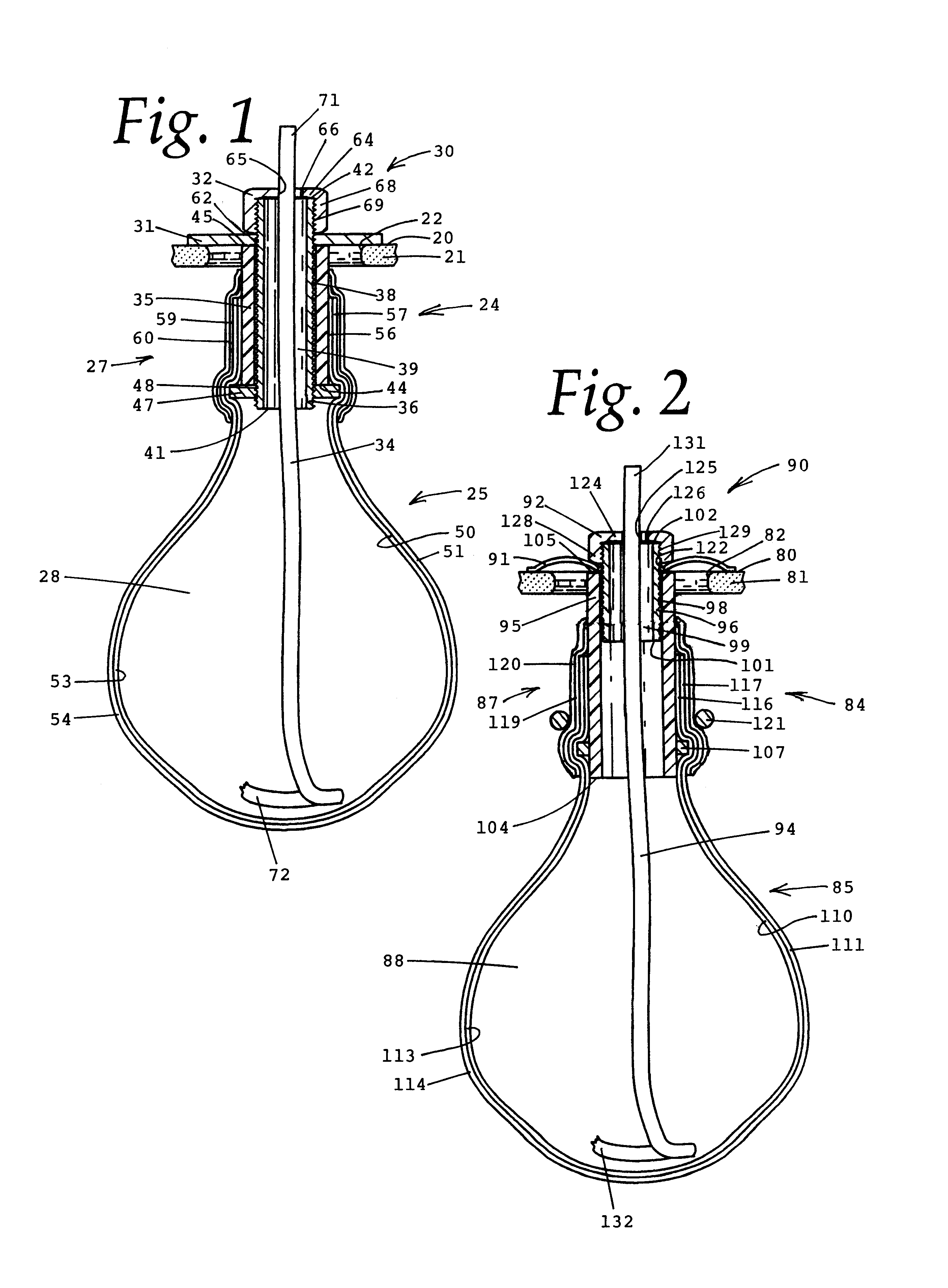
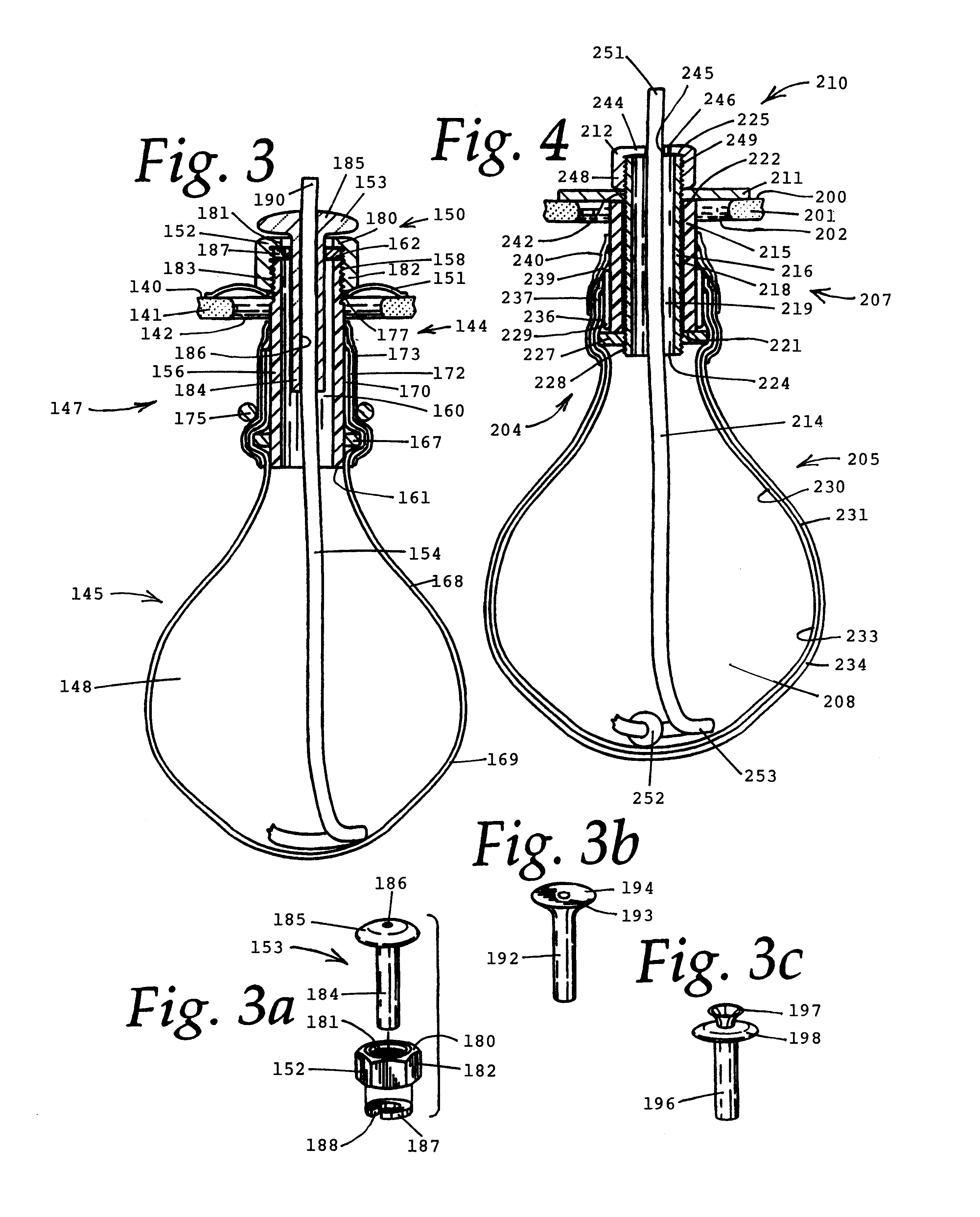
In an exemplary embodiment of the invention, the fuel container is a flexible bladder secured to the tube. A second flexible bladder may surround the first bladder to decrease the chances of fuel leakage caused by rips or punctures to the bladders. The bladders are attached to the underlying tube by tape, heat shrink tubing, clamps, or other means. The tube has a flange ring, or other structure, underlying the bladders to further hold the bladders onto the outside of the tube.
In another exemplary embodiment, a band of insulation may be provided between the tube and the bladders or between the bladders and the heat shrink tubing to prevent damage to the bladders which may be caused by heat.

Problems solved by technology

While the prior art burners function well for their intended purpose, they cannot easily be adapted for use with pre-existing bases, statuary and the like, which might be made of marble, bronze, or ceramic.

Method used


Image

  • Liquid fuel burner
  • Liquid fuel burner
  • Liquid fuel burner

Examples


Embodiment Construction

Referring to the drawings, FIGS. 5 through 10 show various applications for the different embodiments of the oil burners described herein. FIG. 6 shows the oil burner suspended at the top of a church steeple. FIG. 7 shows a large number of oil burners suspended in the various side extensions of a pyramid-shaped candle tree. FIG. 8 is an oil burner replacing the torch held aloft by the right hand of a statue resembling the "Statue of Liberty" found in New York harbor. FIG. 9 is an oil burner suspended in the fireplace at the base of a chimney in a small replica of a room, which has a model of a Christmas tree, a chair and a table. FIG. 10 shows three oil burners placed in a common base, which is a statue depicting the "Last Supper." FIG. 5 shows a different version of the invention wherein nine burners are attached to a common bladder that has been formed with nine extending necks. Obviously, an oil burner constructed in accordance with the invention of the applicants can be used wit...


PUM


Abstract

A liquid fuel burner adapted to be inserted into an opening of a supporting base, such as a statue or other art work, includes a container to hold combustible fuel, a tube having one end attached to an opening in the container, a collar assembly secured to the other end of the tube and having a cap closing the end of the tube and a flange part to support the burner in the opening, and a wick extending from the container through the tube and being held within an opening defined in the cap. The cap may include a glass wick holder to support the wick in burning position thereabove. The fuel container may be defined by one or more flexible bladders which are attached to the tube by insulation, tape, heat-shrink tubing, or a wire clamp.

Description

1. Technical FieldThis invention relates generally to a liquid fuel burner and, more particularly, to a removable liquid fuel burner fittable into a base structure and having a refillable fuel-holding container.2. Background ArtIn the prior art, oil burners and oil lamps are well-known. The following United States patents are representative of the prior art and illustrate many of the devices that have been used in the past.In Bennett, U.S. Pat. No. 13,860 entitled "Lamp" issued Nov. 27, 1855, a fluid lamp is shown wherein an india rubber or elastic bag is placed inside an ordinary lamp and is lined with gutta percha or other substance which protects the bag from chemically reacting fluid fuel. The liner is attached to the inside periphery of a top which has a pair of wick tubes.In Lowe, U.S. Pat. No. 28,436 entitled "Vapor Lamp" issued May 29, 1860, a vapor lamp has a two-part base enclosing a wire-woven bag filled with gas-absorbing cotton material in contact with strands of wick a...

Claims


Application Information

Patent Timeline
Patent Type & Authority Patents(United States)
IPC IPC(8): F23D3/00F23D3/08F23D3/18F23D3/24
CPCF23D3/08F23D3/24F23D3/18
Inventor TAUBITZ, ROBERTTAUBITZ, ROBERT D.TAUBITZ, RONALD
Owner TAUBITZ ROBERT
Why Eureka
Try Eureka