Product diverting mechanism in packaging system

a technology of product diverting and packaging system, which is applied in the direction of packaging, conveyor parts, rollers, etc., can solve the problems of difficult operation of diverting operation and inability to maintain constant position of products after diverting operation

Inactive Publication Date: 2003-06-24
ISHIDA CO LTD
View PDF16 Cites 2 Cited by
  • Summary
  • Abstract
  • Description
  • Claims
  • Application Information

AI Technical Summary

Benefits of technology

While the assignee of the present invention has filed an application for patent in Japan on an invention of a mechanism capable of increasing the diverting speed, another important object of the present invention is to provide the product diverting mechanism of the type referred to above which can perform a diverting operation assuredly and reliably even though the products to be diverted have a varying height.
If in this structure the weight of the movable plate is utilized to avoid the undesirable upward shift of the product, a meritorious effect can also be obtained in that the urging force acting on the products can be retained at a substantially constant value.

Problems solved by technology

However, if the force containing the horizontally acting force component is applied by the force applicator in the direction transverse to the direction of transport, and where the applied force contains a vertically acting force component, there is a possibility that the product applied with such force will "float" above the transport path, resulting in difficulty to accomplish the diverting operation.
In particular, where the diverting speed at which the diverting of the product is executed is increased, the product will float above the transport path by the action of the force applied by the force applicator to the product with the horizontally acting force component no longer acting on the product sufficiently and, therefore, there is a high possibility that the position of the products after having been diverted will not be constant.

Method used


Image

  • Product diverting mechanism in packaging system
  • Product diverting mechanism in packaging system
  • Product diverting mechanism in packaging system

Examples


Embodiment Construction

Hereinafter, a preferred embodiment of the present invention will be described with reference to the accompanying drawings.

System Overview:

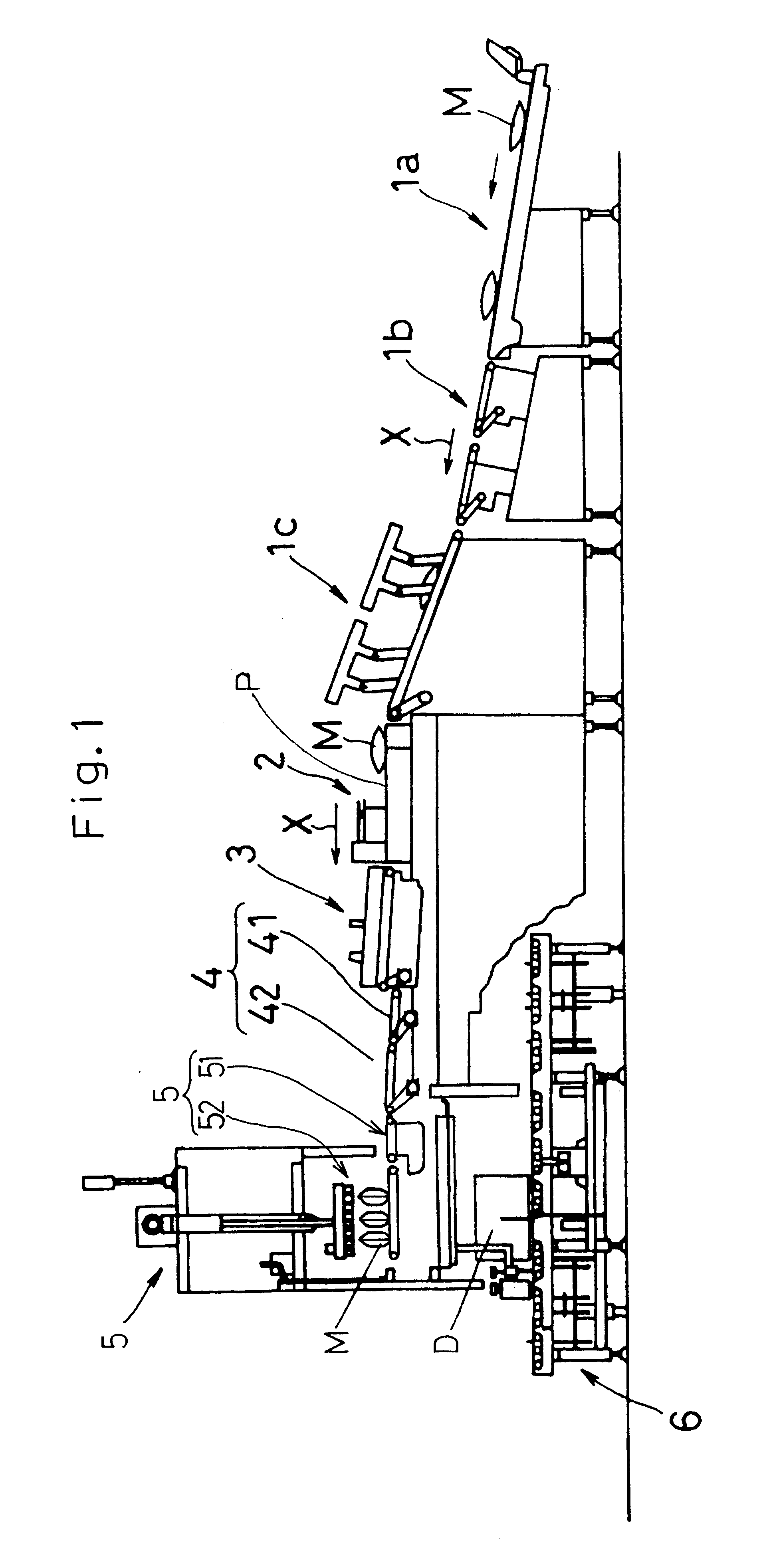
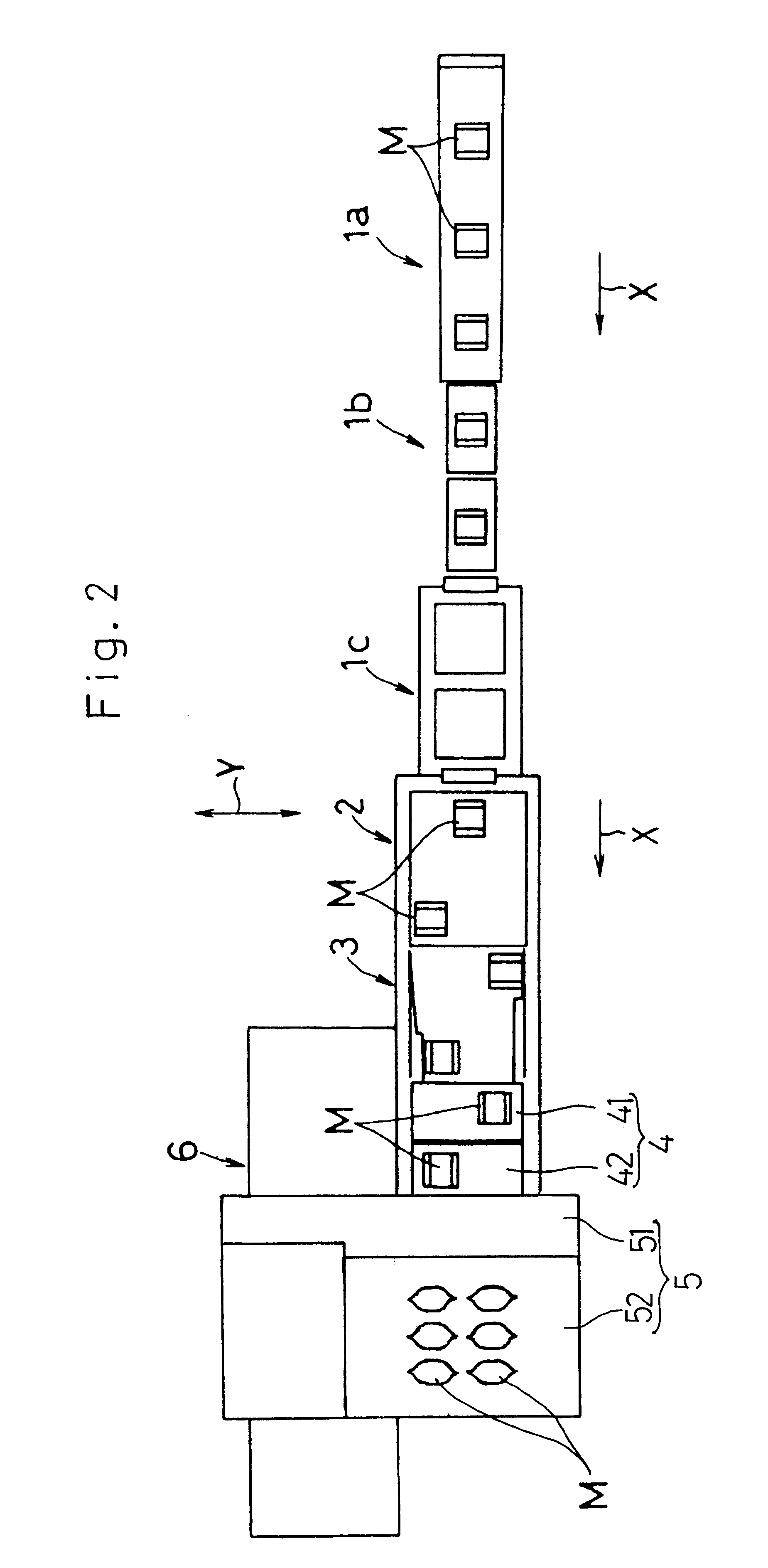
The packaging system embodying the present invention in its entirety is schematically shown in FIGS. 1 and 2. The packaging system shown therein is so designed and so configured as to perform inspection of sealed bags (products) that are successively supplied to an inspecting station, one at a time to determine if the weight of each of the sealed bag meets a required weight and also to determine the presence or absence of a defective seal in each of the sealed bags inspected and as to successively package into a corrugated cardboard box only the sealed bags which have been deemed acceptable. The products to be packaged are those supplied from a preceding processing station where a weighing and bagging system is installed and each containing a predetermined weight of commodities such as, for example, fried potato chips filled and sealed in a respe...


PUM


Abstract

A product diverting mechanism used in a packaging system, which is effective to increase the speed at which the products are successively diverted, includes a force applicator for applying a force, including a force component acting in a horizontal direction, to the products transported from a preceding station, in a direction transverse to a direction of transport of the products, a suppressor disposed above a transporter for suppressing an upward shift of the products which occurs when the force applicator applies the force to the products, and an elevator for moving the suppressor up and down. The suppressor is lowered during an operation to divert the products so as to contact an upper surface of the products.

Description

1. Field of the InventionThe present invention generally relates to a packaging system and, more particularly, to an improvement in and over a product diverting mechanism used in the packaging system.2. Description of the Prior ArtPrior to shipment of products manufactured at a factory to wholesale stores and retail stores, it is a customary practice to package predetermined numbers of the products in corrugated cardboard boxes. While this packaging operation is often carried out by hand, various packaging systems that automate the packaging operation have also been suggested.Such automatic packaging system is generally of a design in which a plurality of products that are lined up are sucked upwardly by, for example, a vacuum suction unit and are then stacked one above the other. In such case, where the products are arranged in a single row, suction and stacking are performed a considerable number of times. Accordingly, in order to reduce the cycle time per box, it can be contempla...

Claims


Application Information

Patent Timeline
Patent Type & Authority Patents(United States)
IPC IPC(8): B65B35/24B65B35/00B65G47/53B65G47/54B65G21/20B65G47/28B65G47/68
CPCB65B35/24B65G47/54B65G21/209
Inventor YOKOTA, KAZUMASAYOKOTA, YUJI
Owner ISHIDA CO LTD
Why Eureka
Try Eureka