Communication method for packet switching systems

a packet switching and communication method technology, applied in the field of communication methods for packet switching systems, can solve the problems of increasing the cost of the switch, and the inability to scale the number of nodes in the out of band scheduling

Inactive Publication Date: 2003-06-24
PMC-SIERRA
View PDF15 Cites 126 Cited by
  • Summary
  • Abstract
  • Description
  • Claims
  • Application Information

AI Technical Summary

Problems solved by technology

1. Output buffered architectures which associate data storage with the transmit side of a port of a node. This structure simplifies input ports since data can be sent directly from the receive port of the node to its output port without scheduling or storage. However, the switching fabric of the network which interconnects ports must have excess bandwidth approaching twice the port bandwidth per attached port. In addition, the output port must have all the scheduling, storage and ordering capabilities of the switch since there is no other inherent way in the node to control traffic destined for the output port.
2. Input buffered switches which store data immediately on the receive side of the port. This eliminates the complexities of the output buffered switch with respect to speed and overlay traffic control. Data can be stored independently of the state of the other ports or the state of the interconnecting switching mechanism. However, for this type of switch, the state of the output port must be known before the data can be sent through the switching interconnection.
However, distributed schedulers would require buffering on both input and output ports that would greatly increase the cost of the switch.
Whether distributed or centralized, out of band scheduling cannot be scaled in number of nodes, and therefore is inflexible.

Method used


Image

  • Communication method for packet switching systems
  • Communication method for packet switching systems
  • Communication method for packet switching systems

Examples


Embodiment Construction

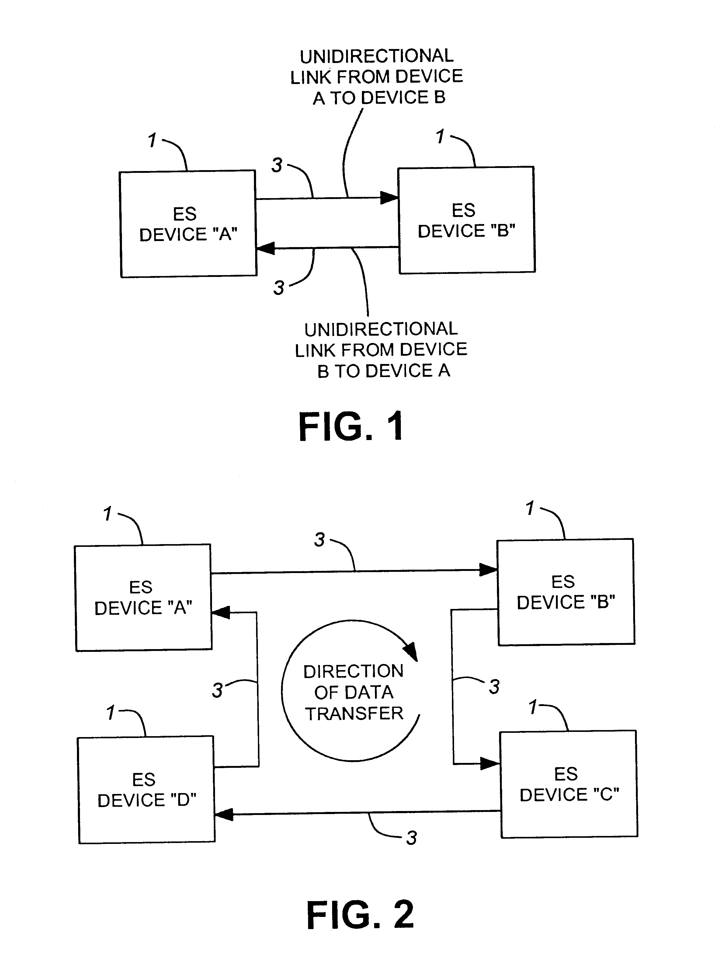
Turning to FIG. 1, a simplest form of a network comprising a pair of nodes 1 is shown, which are interconnected by a pair of unidirectional links 3 (transmission paths) which carry data in opposite directions from each respective node to the other. The nodes are labelled and are referred to as end systems (ES) (as distinct from switching devices which merely route data, and which are referred to as intermediate systems (IS)).

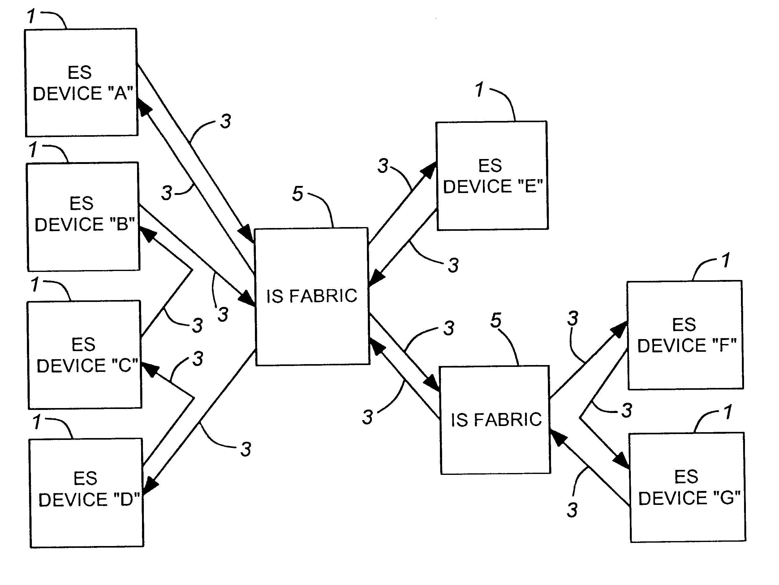
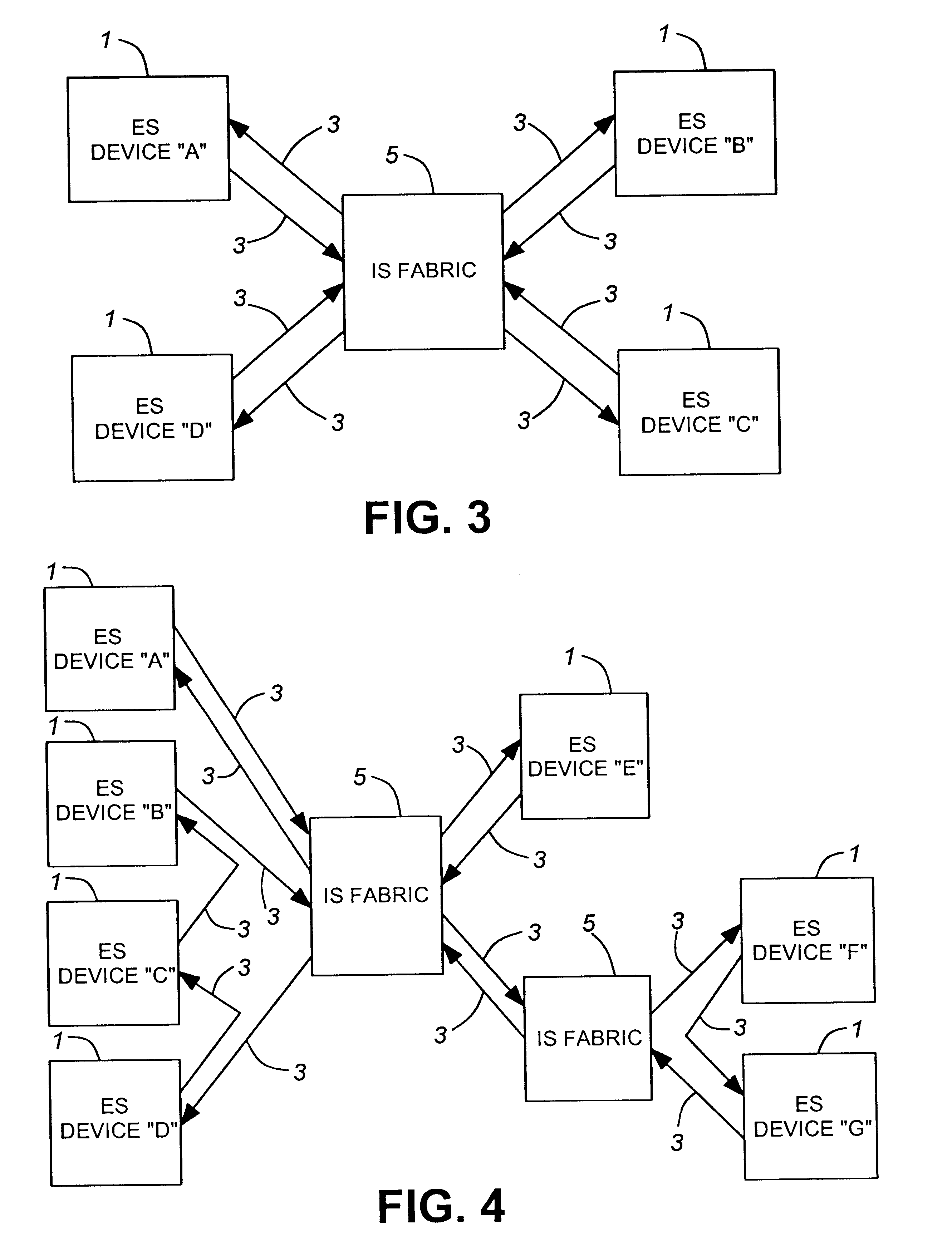
FIG. 2 illustrates four nodes 1 which are interconnected in a ring network, with the egress port of one node coupled to the ingress port of the next via unidirectional transmission links 3.

As may be seen, the unidirectional nature of message flow exists with only four point-to-point links being used to connect the four nodes (devices). The ES devices bypass or forward messages from their ingress to their egress ports if they determine, by inspecting the destination addresses carried within the messages, that it is necessary to do so. Thus a message originating a...


PUM


Abstract

A method of communicating data frames between nodes in a network comprised of one or more end system nodes where each end system node has a unidirectional ingress port and a unidirectional egress port. The method comprises transmitting a data frame from an egress port of one end system node to the ingress port of another end system node, the receiving end system node then determining whether it is the final destination for the data frame. If the receiving end system node is the final destination of the data frame, the receiving end system node absorbs the message. If not, the receiving end system node buffers and then retransmits the data frame through its own egress port. The method provides scalability, low cost, distributed pipeline scheduling, maximum complexity of the network fabric, and maximum speed.

Description

This invention relates to the field of data transmission, and in particular to a method of routing data messages in a digital switching network.BACKGROUND TO THE INVENTIONData switching networks are generally configured with data transceivers (nodes) connected in ring structures or in star structures. As is well known, in the ring structure, for example, data signals are transmitted around the ring, with each transceiver detecting whether its address is at the head of a frame. If so, it accepts the frame of data. In star networks, there is a central switching system through which each message passes, which detects the addresses and routes the messages to the particular arm of the star to which the addressed node is connected.Well known switching networks conform to the FDDI, FC and SCI standards, and fall into two general classes:1. Output buffered architectures which associate data storage with the transmit side of a port of a node. This structure simplifies input ports since data ...

Claims


Application Information

Patent Timeline
Patent Type & Authority Patents(United States)
IPC IPC(8): H04L12/56H04L12/427
CPCH04L12/427H04L12/5693H04L47/52H04L47/527H04L49/3018H04L49/3027H04L49/102H04L49/55H04L49/20H04L49/50H04L47/50
Inventor HAGGLUND, BARRY BENJAMINALEXANDER, THOMASLITTLE, VERNON ROBERT
Owner PMC-SIERRA
Why Eureka
Try Eureka