Matched filter

a filter and matching technology, applied in the field of matching filters, can solve the problems of increasing the scale of the circuit, increasing the number of flip-flops, and increasing power consumption

Inactive Publication Date: 2003-06-24
FUJITSU LTD
View PDF8 Cites 8 Cited by
  • Summary
  • Abstract
  • Description
  • Claims
  • Application Information

AI Technical Summary

Problems solved by technology

However, these futures conversely cause the following problems.
Namely, these futures causes an increase of power consumption (1) since the device operates at a high frequency, an increase of the number of flip-flops to be operated (2), and an increase of circuit scale of the spread data path unit (3 and 4) further, from 2 to 4, an increase of scale of the circuit because of the long shift register and adder.
Moreover, since a switching activity in the spread data path unit is very high, the power consumption is increased.
For this, the circuit is excessively concentrated from a viewpoint of circuit structure or layout, so that the layout becomes impossible.
Since the hug spread data path unit is divided, it becomes possible to use a low-speed clock in lieu of a high-speed clock, which leads to a decrease of frequencies of the circuit operation.

Method used


Image

  • Matched filter
  • Matched filter
  • Matched filter

Examples


Embodiment Construction

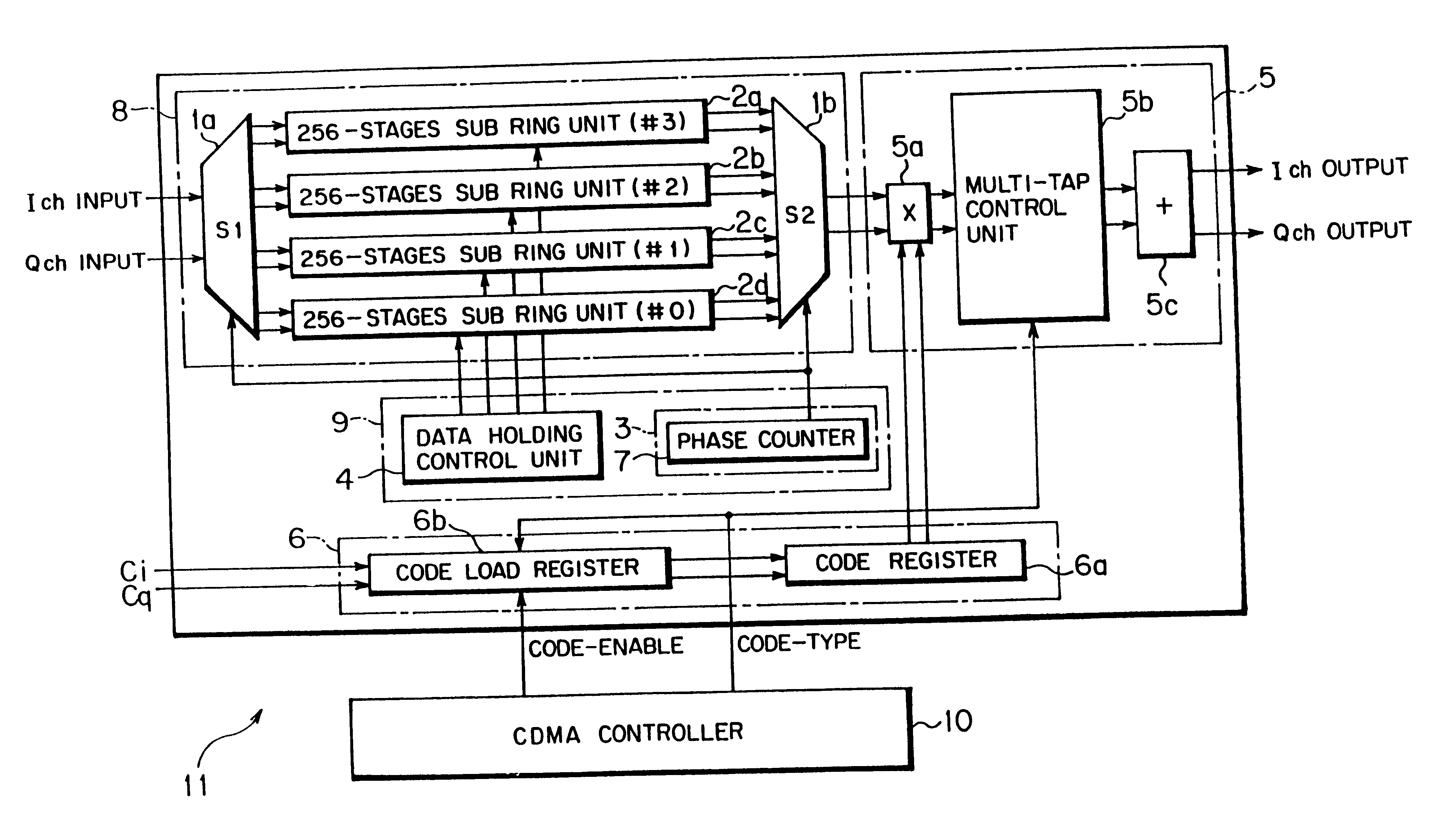
FIG. 1 is a block diagram of a matched filter to which this invention is applied. The matched filter 11 shown in FIG. 1 comprises a CDMA controller 10, a spread data path unit 8, a spread data path input control unit 9, a spreading code setting unit 6 and an arithmetic unit 5.

For the sake of description hereinafter, concrete numeral values used in the matched filter 11 to which this invention is applied are as follows. The number of taps is T=256, corresponding to a length of the used spread code. The number of times of over-sampling O is the number of times of over-sampling performed within one chip duration, set to O=4. The number of spread data path bits D represents a width of data of bits equal in number to a modulation multivalue in the primary modulation, set to D=6. The data is transmitted and received with 6 bits as representation of two's complement. In addition, the chip rate is 4 MHz, and one chip duration is a reciprocal thereof.

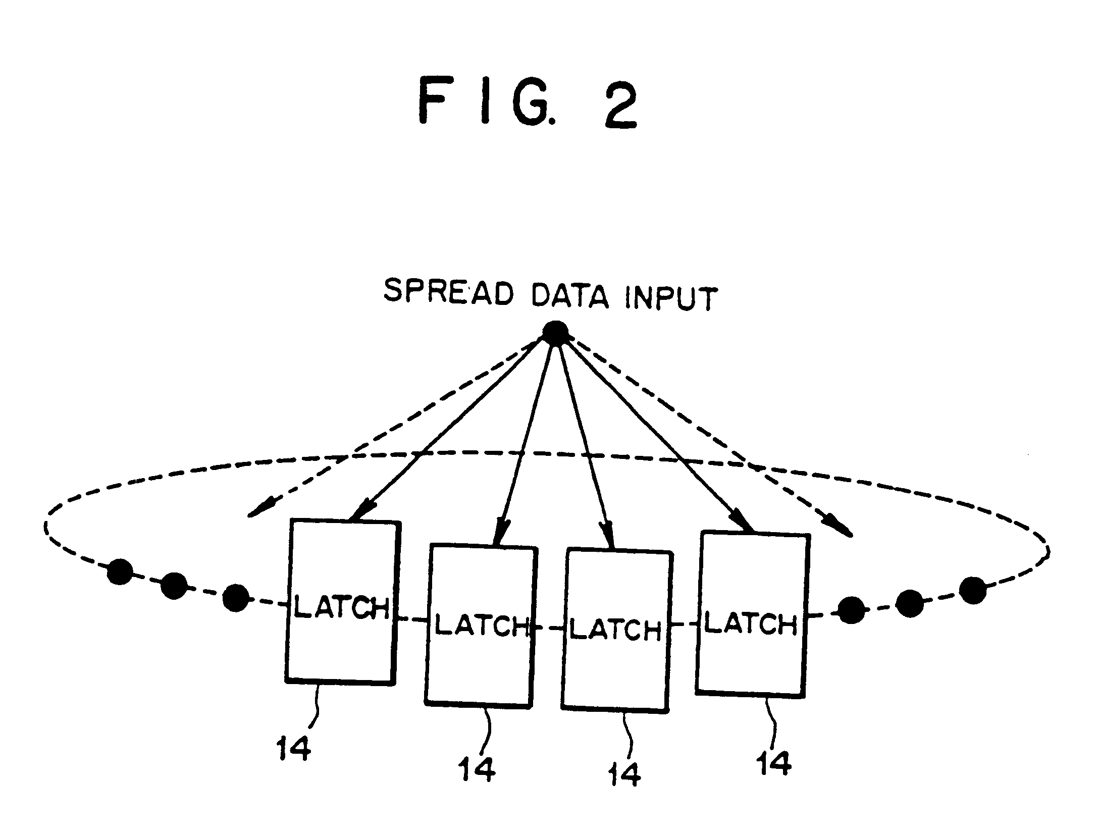
The spread data path unit 8 shown in FIG....


PUM


Abstract

In a matched filter, a spread data path unit holds inputted spread data, a multiplier unit multiplies an output of the spread data path unit by a spreading replica code, and an adder unit adds results of the multiplication and outputs an added result. The spread data path unit comprises a first selector being able to selectively output the spread data, a plurality of sub spread data path units each having a plurality of latch circuits temporarily holding the spread data from the first selector, and a second selector being able to selectively output outputs from the sub spread data path units, whereby a circuit scale of the spread data path unit is decreased.

Description

(1) Field of the InventionThe present invention relates to a matched filter suitable for use in a radio receiver adopting direct sequence code division multiple access.(2) Description of Related ArtIn direct sequence code division multiple access (DS-CDMA [Direct Sequence Code Division Multiple Access]), the transmitter primarily modulates a data code in, for example, QPSK (Quadrature Phase Shift Keying), spreads a bandwidth thereof using a spreading code, and transmits the data code. On the other hand, the receiver cross-correlates using the same spreading code as in the transmitter to detect a peak of the correlation value, performs acquisition and tracking, and demodulates by correlation detection.FIG. 11(a) is a block diagram of a transmitting unit of a radio terminal in DS-CDMA using QPSK. In the transmitting unit 30 of the radio terminal in DS-CDMA shown in FIG. 11(a), a data code is QPSK-modulated in a primary modulating unit 30a, a bandwidth of the signal is spread with an P...

Claims


Application Information

Patent Timeline
Patent Type & Authority Patents(United States)
IPC IPC(8): H04B1/707H03H17/02H04B1/7093
CPCH04B1/7093H04B2201/70707
Inventor CHEN, BENUCHISHIMA, MAKOTO
Owner FUJITSU LTD
Why Eureka
Try Eureka