Tractor trailer gap treatment

a trailer and gap treatment technology, applied in the direction of roofs, transportation and packaging, vehicle arrangements, etc., can solve the problem that none of these was too practicabl

Inactive Publication Date: 2003-07-01
INT TRUCK INTPROP LLC
View PDF10 Cites 40 Cited by
  • Summary
  • Abstract
  • Description
  • Claims
  • Application Information

AI Technical Summary

Problems solved by technology

None of these was too practicable.

Method used


Image

  • Tractor trailer gap treatment
  • Tractor trailer gap treatment
  • Tractor trailer gap treatment

Examples


Embodiment Construction

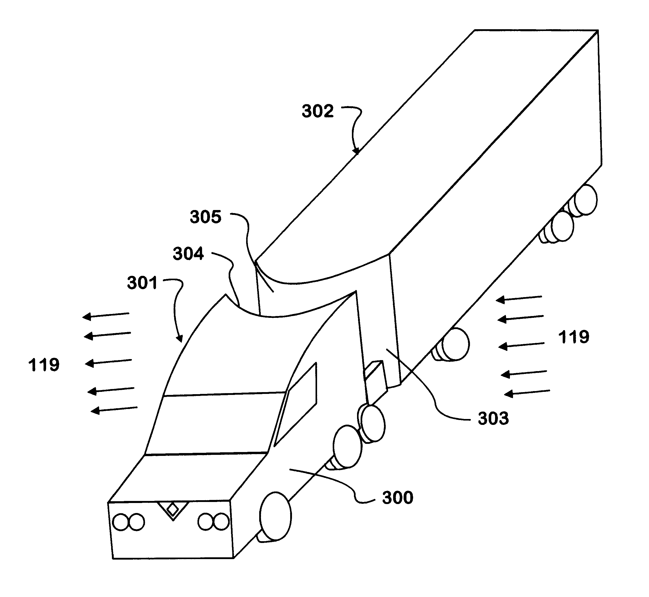
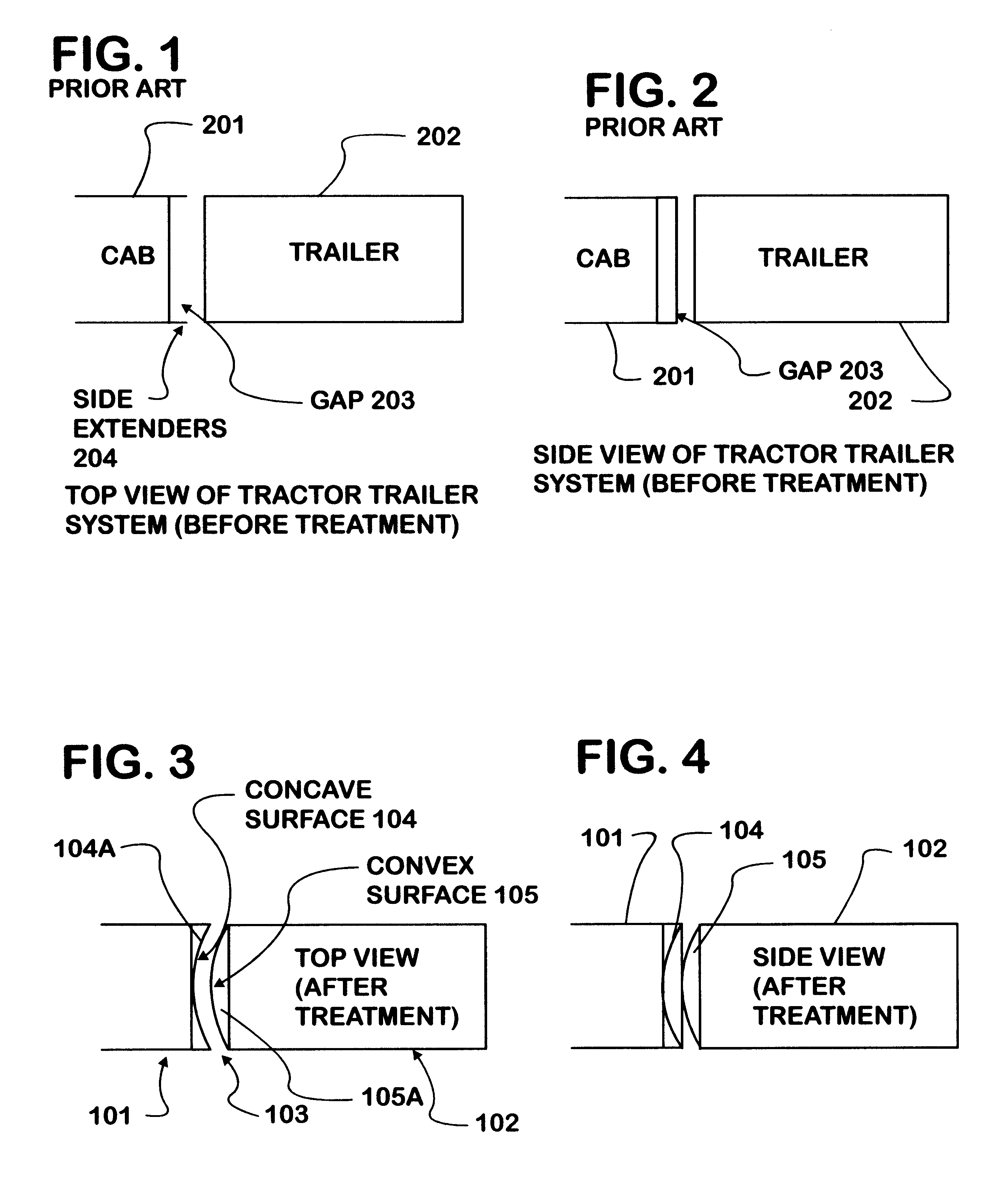
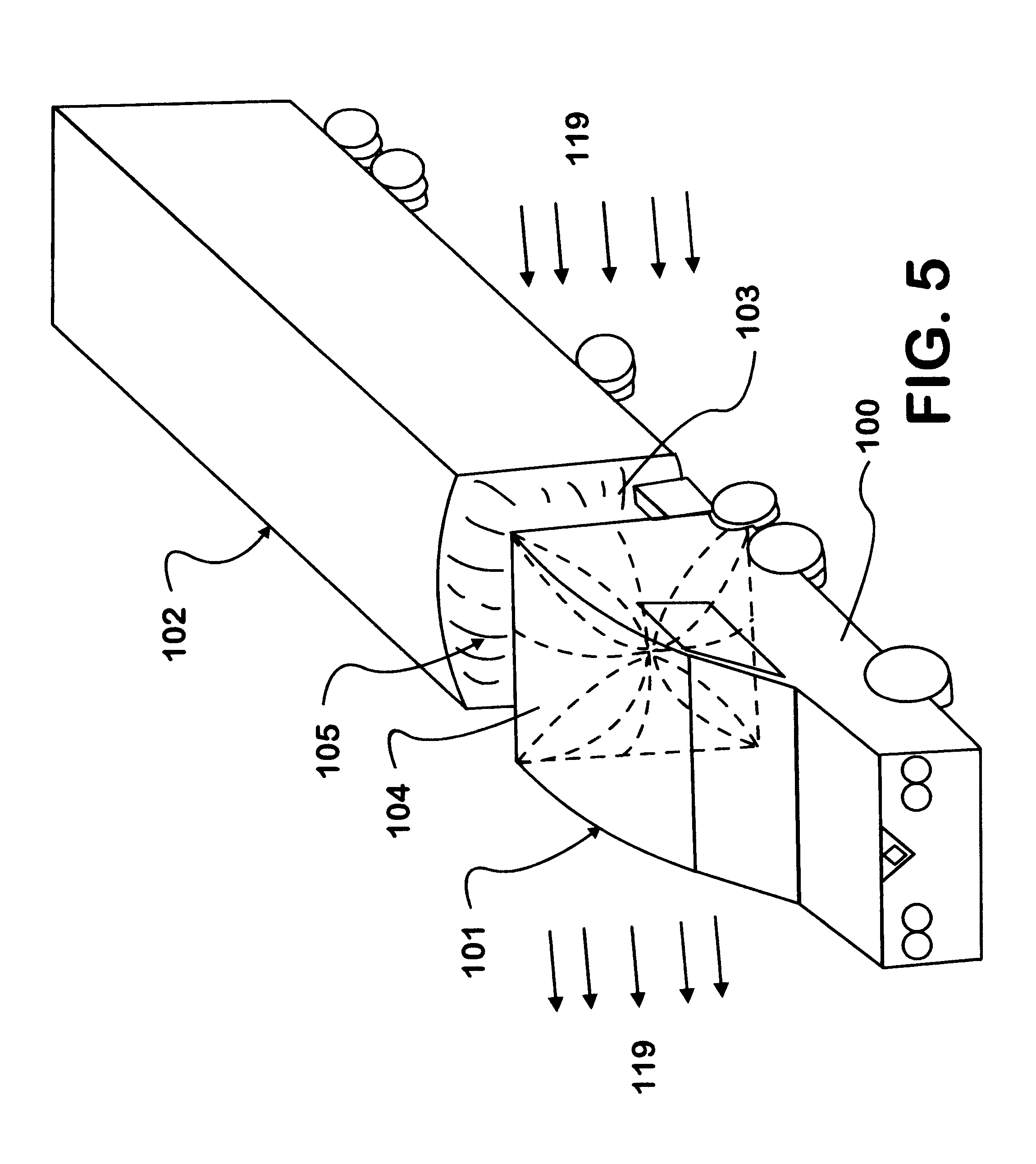
The cab 101 of the tractor or towing vehicle 100 is shown joined to a trailer 102 or other towed vehicle in FIGS. 3 to 5. The towing vehicle 100 may be a heavy-duty truck or any vehicle capable of towing a trailer such as a pickup truck, a mobile home or other recreational vehicle. The trailer 102 may be one of many kinds of towed vehicles such as a camper. The language of this document refers to the towing vehicle 100 as a tractor but it is understood that it may not strictly be limited to being a highway tractor as the towed vehicle or trailer 102 may not limited to a commercial load carrying trailer. The tractor-trailer system of this invention uses aerodynamic principles to use crosswind to its advantage. The system has a curvilinear duct 103 by having a attaching a convex surface 105 on the trailer 102 front and a concave surface 104 on the back of the cab 101. When a cross wind 119 enters the gap 103, it creates a negative pressure (compare to ambient) on the convex surface 10...


PUM


Abstract

A tractor-trailer system uses aerodynamic principles to use crosswind to its advantage. The system has a curvilinear duct by having a attaching a convex body on the trailer front and a concave body on the back of the cab. When a cross wind enters the gap, it creates a negative pressure (compare to ambient) on the convex surface (trailer front) and a positive pressure on concave surface (back of the cab). Both of these pressures will help reduce the drag. Further having the crosswind flow smoothly can lead to less turbulence intensity in the gap, which can help in improving handling qualities of the system. There is a similar situation both for drag as well as handling qualities can be given for the air traveling in vertical direction (even at zero cross wind).

Description

This invention relates to the aerodynamics of a mobile vehicle, specifically the gap between a powered vehicle and pulled trailer. Examples would include a tractor-trailer heavy-duty truck and a towed mobile home. The gap between a tractor and trailer plays an important role in the overall performance the system during a cross wind. It affects drag as well as the handling quality of the vehicle and trailer combination.PRIOR ARTIn the prior art there have been attempts to close up the gap between the rear of the tractor and the front of the trailer. None of these was too practicable. An example is shown in FIGS. 1 and 2. The cab 201 of the tractor-trailer has side extenders 204 which extend to cover the gap 203 between the cab 201 and the trailer 202. Other prior art concepts included changing the shape of the front of the trailer to reduce overall aerodynamic drag. U.S. Pat. Nos. 4,021,069 and 4,702,509 are examples of this approach.What is needed and does not exist in the prior art...

Claims


Application Information

Patent Timeline
Patent Type & Authority Patents(United States)
IPC IPC(8): B62D35/00
CPCB62D35/001
Inventor JAIN, SUNIL K.
Owner INT TRUCK INTPROP LLC
Why Eureka
Try Eureka